1-Visitor
December 5, 2019
Solved

PTC_CONSTRAINT_SET and distance calculation

  • December 5, 2019
  • 17 replies
  • 7984 views

Hi,


I have made a simple test assembly to show how components with PTC_CONSTRAINT_SET don't always behave the way I want/expect them to. I want to be able to add/remove/configure components quickly and have used a combination of PTC_CONSTRAINT_SET and distance calculations to achieve this. This assembly consists of four parts - cube, sphere, pyramid and cylinder placed on a fifth part called ground. The four parts can be added or removed based on the value of connected parameters called cube, sphere, pyramid and cylinder. The pyramid and cylinder parts can also change orientation by changing the value of parameters PYRAMID_ORIENTATION and CYLINDER_ORIENTATION. Can someone please have a look at the attached assembly PTC_CONSTRAINT_SET.asm and tell me why the parts behave the way they do? 


Initially, the assembly looks like this:
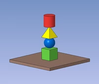
Model1.PNG


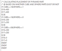
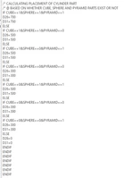
Here is the complete relations text in PTC_CONSTRAINT_SET.asm
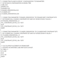
Relations1.PNGRelations2.PNGRelations3.PNG


Here are the available values for configuration parameters. I have also added planes with the same names in a group called configuration for easy configuration - you can change the parameter values easily by changing the values of these planes.
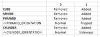
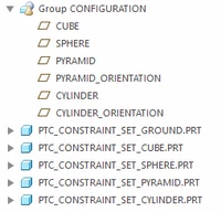
PTC_CONSTRAINT_SET_OPTIONS.PNG

MODEL TREE.PNG

(The values are initially set to CUBE=1, SPHERE=1, PYRAMID=1, PYRAMID_ORIENTATION=0, cylinder=1 and CYLINDER_ORIENTATION=0).


If I remove the cube part (change value of cube to 0) and click regenerate, the assembly looks like this:
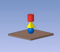
Model2.PNG

If I change the orientation of the pyramid part (change value of pyramid_orientation to 1), it looks like this:
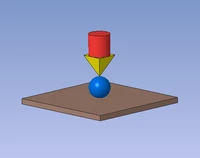
Model3.PNG

Finally, changing cylinder_orientation to 1 makes it look like this:
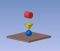
Model4.PNG

The cylinder part is misplaced and regenerate doesn't do anything, but if I either click edit definition or resume/suppress, the assembly looks like this:
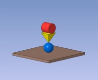
Model5.PNG


At first, I made the assembly without the cylinder part, but the model would only get stuck occasionally and I could not seem to reproduce it consistently, so I added another part with PTC_CONSTRAINT_SETs and now it gets stuck very often. It will get stuck in certain combinations and regenerate doesn't do anything, can someone please tell me why? How does regenerate and edit definition consider placement differently? This is obviously not a huge problem with this simple assembly, but I am trying to use the same method for more complex assemblies and that causes more problems. As I already wrote, the more components with PTC_CONSTRAINT_SETs, the messier it gets. Any suggestions?


Thanks,

Avero


Edit: I am using Creo 5


Screenshot of Model intent -> Program
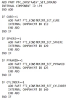
Program.PNG

Best answer by TomU

Latest update from tech support:


"A fix to this SPR has been submitted to Creo 6.0.4.0 which is scheduled for release mid-late February.  After retrieving the assembly, edit the definition of the cylinder part and complete and the process outlined in the case and post will behave as expected – the cylinder will use the correct placement location and orientation."

17 replies

23-Emerald IV
December 5, 2019

It might be quicker to let PTC technical support look at this.  Do you have active maintenance?  If not, I'm more than willing to submit this to them and see what they say...

23-Emerald IV
December 5, 2019

I can reproduce the issue with Creo Parametric 6.0.3.0.  I tried moving the relations into their respective components and features, but it didn't make any difference.  After the last orientation change, the correct set seems to be active, and the value is correct, but the model is not snapped to the position specified by the set.  For some reason it continues to stay at the last position of this set when it was last active.  I think PTC will need to take a look at this.

23-Emerald IV
December 5, 2019

I'm going to open a case...

avero1-VisitorAuthor
1-Visitor
December 6, 2019

Thank you!

12-Amethyst
December 6, 2019

another option would be to create coordinate systems for each of the components and constrain to them. now write your relations to move around the coordinate systems.

question, when using multiple constraint sets and you rotate that component, don't you get invalid constraints during the edit definition? 

23-Emerald IV
December 6, 2019

@jbob wrote:

question, when using multiple constraint sets and you rotate that component, don't you get invalid constraints during the edit definition? 


No, because the first constraint set is completely disabled when the second set is enabled.  The two sets don't fight with each other since only one set is active at a time.

19-Tanzanite
December 6, 2019

Hi, this remains an interesting unsolved case.

I can't open your Creo5 file so tried to make toy example similar to your new example - using similar structure of assembly level relations & pro/program code to drive constraint sets and existence of components.


Except I didn't use a value of a dimension to determine the logic of whether a component exists or is rotated - I defined Yes/No assembly level parameters:

ptc_constraint_set_demo-1.png


Toggling these yes/no parameters and regenerating seems to work just fine.  Please try the attached model yourself.


So your code should work, I think, but there is something wrong:

- something in your assembly constraints that gives problems?  unlikely as re-edit-definition fixes the connections without picking new references


- using dimensions (real numbers) to define On/Off states - round-off errors causing the logic to fail?  - again, unlikely because it seems that the correct offset values and constraint set names are being set.


- bug ? - nah, this is PTC software 🙂 


23-Emerald IV
December 6, 2019

Forcing a model player regen also fixes the issues with the original model.  That's why I wondered if it was a regeneration order issue.  Unfortunately I wasn't to find anything like that, even after reordering a bunch of stuff.