1-Visitor
February 13, 2013
Solved

Reference/display dimensions from part in an assembly drawing

  • February 13, 2013
  • 2 replies
  • 17345 views

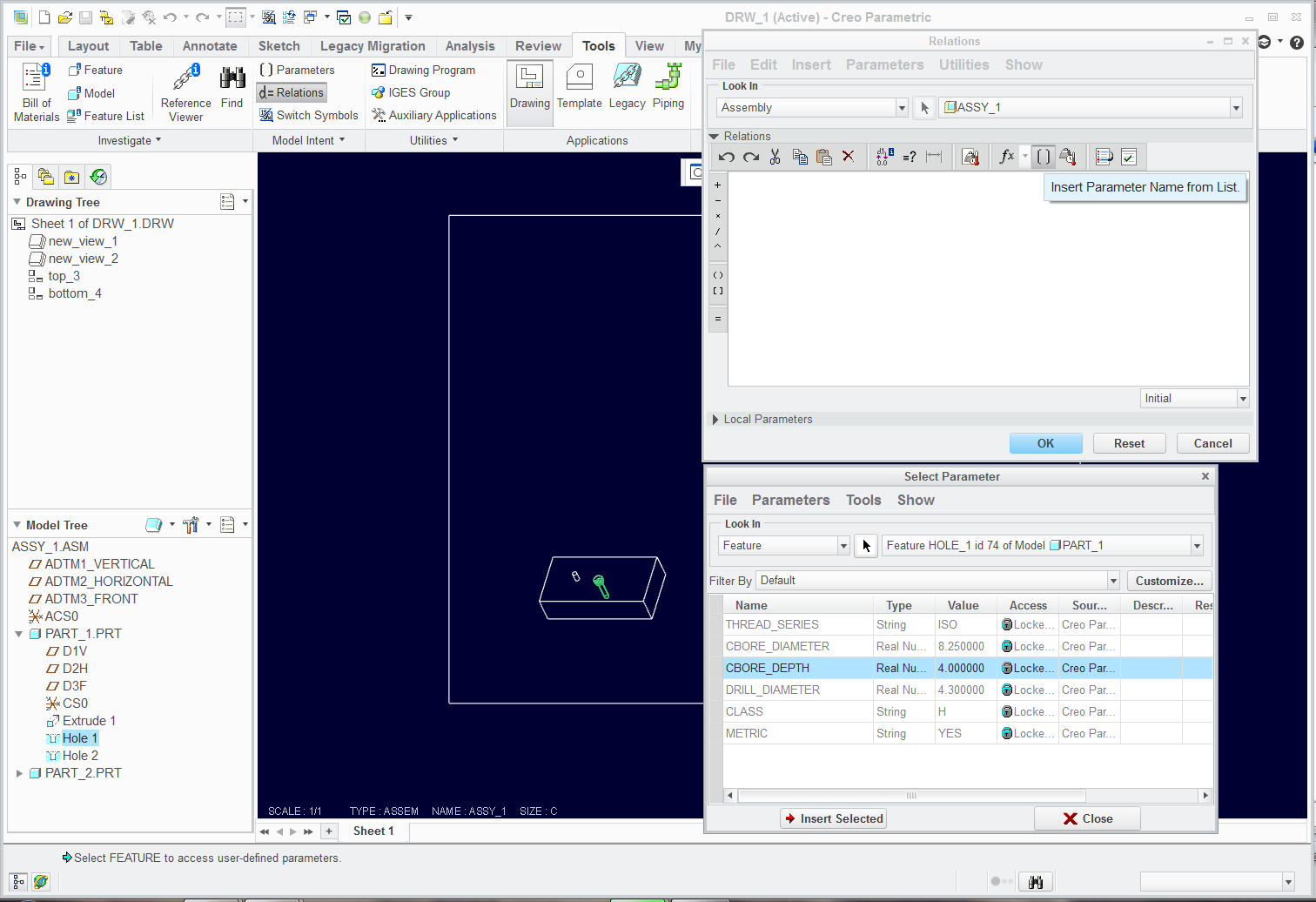
How do you display a dimension on an assembly drawing that references a dimension from a feature in a part of that assembly?

I've tried

&d###:file_name

&d###:file_name.prt

&d###:feature_number:file_name

I am trying to dimension a counter bore hole callout for a part in an inseparable assembly.


Thanks


This thread is inactive and closed by the PTC Community Management Team. If you would like to provide a reply and re-open this thread, please notify the moderator and reference the thread. You may also use "Start a topic" button to ask a new question. Please be sure to include what version of the PTC product you are using so another community member knowledgeable about your version may be able to assist.
Best answer by TomD.inPDX

I am not sure if WF4 has the same or similar interface to Creo that is why I didn't add it... but there is a button in Creo that lets you get to all the parameters of any feature, part, assembly, etc.

See if any of this looks familiar. You should have an Insert Parameter button somewhere... you should have the features shown in the model tree (for ease of use)... and you select the feature in the Parameter list and Insert Selected. Then you build the relation you want.

Snaggin_a_parameter_into_relations.png

2 replies

17-Peridot
February 13, 2013

Show Annotation and pick the part or feature in the model tree. Once you show it, you can get the code by with Switch Symbols.

Sublevel_dim.JPG

17-Peridot
February 13, 2013

I guess the syntax is &dnnn:N where "N" is the assigned number to each part in the assembly, not specifically tied to the part itself. This makes sense when you have multiples of the same part, I guess.

Tim11-VisitorAuthor
1-Visitor
February 13, 2013

2-13-2013+2-44-54+PM.png


Tony, the above syntax you offered isn't working. See picture for clarity.

I'm trying to reference d259 in part 181750-01 in the tree.

I've tried

&d259:5

&d259:52

&d259:1

It just takes the & sign away from the note on some of the attempts.

We've been trying to figure this out for a while... Any help would be appreciated.

Tim11-VisitorAuthor
1-Visitor
February 14, 2013

Everything you wrote echos what I'm seeing.

Showing a dimsion, your 3rd bullet, does work correctly and that will work for us. The only problem with that is you cannot place GD&T on that dimension using datums from the Assembly. Which is probably better practice to place th datums in the part, rather than the assembly anyway.

It would be nice to know how to add these dimensions in a drafting dimension still.

Thanks,

Tim11-VisitorAuthor
1-Visitor
February 14, 2013

The relations worked also. Do you have a reference website or document explaining the syntax of the relations? I'm unclear why

VALUE1=CBORE_DIAMETER:FID_74:0

VALUE2=CBORE_DEPTH:FID_74:0

was typed the way it was.


Thanks

17-Peridot
February 14, 2013

I am not sure if WF4 has the same or similar interface to Creo that is why I didn't add it... but there is a button in Creo that lets you get to all the parameters of any feature, part, assembly, etc.

See if any of this looks familiar. You should have an Insert Parameter button somewhere... you should have the features shown in the model tree (for ease of use)... and you select the feature in the Parameter list and Insert Selected. Then you build the relation you want.

Snaggin_a_parameter_into_relations.png