12-Amethyst
December 17, 2015
Question

Visualizing threads on 3D models with Creo

  • December 17, 2015
  • 4 replies
  • 15698 views

Hello

in my past experience, designers have to make a compromised when designing a component with threads.

Either they will use the cosmetic thread functionality which allow to represent the thread in 2D very quickly and efficiently but in 3D, the sruface still remain very flat.

Or 3D features could be created on the 3D models showing the thread but when comes 2D, the drawing looks very bad....  In addition creating the thread in 3D add weight to the file.

So in an assembly with many components having threads you end up with a lot of data to download/upload.

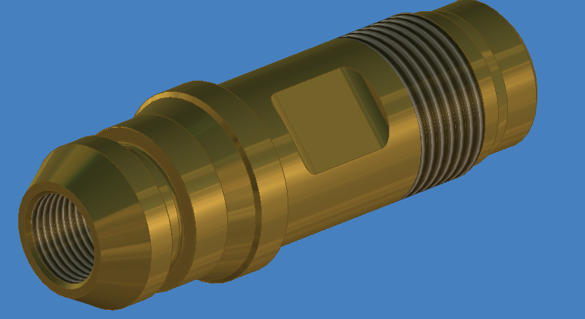
Here is a screenshot from Inventor. It is just an image on the 3D model which is automatically placed when selecting thread. It does not add any weight to the file and it is understood as thread for the 2D drawing. When vizualizing the 3D model it is obvious that we have a thread here. It helps understanding the design.

Inventor.PNG

What is PTC solution as I really do not see any improvement even with Creo 3.  The Intelligent Fastener seems to be only for standard hardwares.

Thanks

Best regards


This thread is inactive and closed by the PTC Community Management Team. If you would like to provide a reply and re-open this thread, please notify the moderator and reference the thread. You may also use "Start a topic" button to ask a new question. Please be sure to include what version of the PTC product you are using so another community member knowledgeable about your version may be able to assist.

4 replies

14-Alexandrite
December 17, 2015

Sorry, but I don't have a great solution for you.  Personally, I always just model threads at a slightly different diameter than the rest of the shaft, and change the color.  (This makes it easy to determine if you have the right grip length, by observing if the colored portion is sticking out of the hole or not.)  I've never had a need to actually model threads, or show them graphically like in your image.  I suppose you might be able to get a similar effect in Creo by creating a long skinny JPEG of one thread, and applying it as a repeating texture, changing the scale as needed to get the right pitch...  but that seems like a lot of trouble.

You said: "the cosmetic thread functionality which allow to represent the thread in 2D very quickly and efficiently but..."

Could you explain how that works?  I've never seen cosmetic threads show up on a drawing.  I just ran some experiments, and all I could get was a few of the dimensions to appear.  Checked layers, config settings, and drawing detail options...  Online help leads me to believe this functionality may only be intended to work in section cuts, but I couldn't get that to work either.

If this did work, it might be a reason to actually use cosmetic sketches.  We generally don't, as there doesn't seem much point.  I'd thought it was just a poorly implemented way to hold thread metadata...

6-Contributor
December 25, 2015

I use helical sweep for major threads such as ACME threads whose representation is important from drawing point of view. For other threads I use cosmetic threads, As far as representation of the cosmetic threads in the drawing first i draw parametric sketch by using entities of cosmetic thread lines & convert its text style to hidden style if it has been shown on full view.To avoid confusion please don't forget to hide cosmetic threads in model , as cosmetic threads tends to show cross-lines in drawing when directly done by show lines function in layout. And for the dimensional details we can then add dimensions to the sketched entities.

1-Visitor
December 18, 2015

I would like to 2nd Chris's point that there is not a good solution illustrating threads in any version of Creo. This has caused issues with us in manufacturing and assembly. It is too difficult and memory intensive to model threads so we use cosmetic threads and this causes its own round of problems because you cant see the threads on interfacing parts. Not to mention the issues that cosmetic threads have in a drawing. I am familiar with inventors method of handling this and don't understand why PTC cannot implement a similar solution. What I have done in the past just to fake some threads in is to apply the image below to the threaded surface and stretch/shrink. And yes it is a PITA, and it looks like cr@p in drawings.

Custom-Cosmetic-Thread.png

Summary- They're threads.....they have been around a long time.......this shouldn't be that hard.

17-Peridot
December 19, 2015

I grew up with the Pro|E cosmetic threads and I find them very useful!  They are well placed, and even properly trimmed if applied correctly.  I find them useful in wireframe mode where you can easily see the mating thread and determine if you have sufficient clearance on all your fasteners.  Otherwise, yes, they do show up in drawings and yes, sometimes they are a pain to manage in drawings; but that's another subject.

On the flipside, the "texture mapping" method, although perfectly reasonable beyond simply a reserved surface color, comes with a Creo shortcoming... Not the best texture mapping defaults on the planet.  It all depends on how important it is.

I like real threads.  As with all things Creo, specially the core version, it can be done but nothing is automatic.  But I have made this simple for my purposes.

Bottom line; if I need threads, cut them in the part; If I have threads, at least back them with a cosmetic thread if not a more comprehensive hole feature.  I'd like to keep my texture manipulation to a minimum.  Too many lost image links for my comfort... too much file bulk to store them with the part.  Curious about the GPU-cycle tax for textures and decals in a heavy session(?).

1-Visitor
December 19, 2015

GPUs are generally designed to handle textures as these are typically used to substitute for complicated descriptions and computations of displaced surface geometry - as these shaded threads are set to do.

It looks from the OP image that they used circular ridges rather than helical threads as a short-cut.

I would probably use a spiral datum curve if I had to depict them. It is fairly light weight, includes the pitch and OD/ID, does not show through things like the 'cosmetic' thread does, and shows up in all modes. Just make 'hidden removal for datum curves' or whatever the Detail View Property checkbox is.

1-Visitor
December 19, 2015

hi

1-Visitor
December 26, 2015

Hi Chris,

      whatever Antonius has written here is true. It is just a waste of time trying to create threads on the CAD model. It is better that we mention the same thing in the drawing rather than modeling it on the 3D model. The reason is, it is always a drawing given for manufacturing and not a 3D CAD model. Only during special application we do provide a 3D model but again with the drawing.

Regards.

ChrisPLM12-AmethystAuthor
12-Amethyst
January 4, 2016

Hi B M Vinay

I am afraid but I must disagree with your comment. If you want to move your company to more Part/Model centric then you must consider review and approving design without 2D drawings. I actually hoping to get the creation of 2D drawings as part of a background process ie done automatically according to the model statuses.

I have gone close to that goal in my previous company and hope to achieve it in my new company.

Strictly speaking about processes and waste removing, having a file for 3D and a file for 2D is a pure waste. Some company which have only installed 3D, still think 2D and see 3D has a nice feature but a burden and often users take short cut. Those companies who want to move to part/model centric realize that the software still has many limitation as the one which is the topic of this thread.

As a business system manager I have no preferred system. I take the requirements, evaluate, review cost (not only licences, but cost of training, migration, data model changes, etc....) and base the decision on facts. Obviously, it has been decided to move from Inventor to Creo but I know that a core of my user base will give me a hard time because of how poorly Creo handles threads compare to Inventor.  While I can argue that Inventor manages many other functionalities much less efficiently than Creo (obviously otherwise, I would have not recommended to move to Creo), I am trying to find how I can educate my new users.

In addition, as mentioned, how can we do a design review if threads are not easily readable in 3D (and easy to make)......

Thank you all for your comments. I would say that I understand that there is no efficient way to do it with Creo. This has not changed for a very long time. (I had implemented Creo (actually up to Creo Element) in the past. I see that in 3 new released of their product PTC still have not made any improvement in that area.

I wonder why.   I was in Stuttgart in November, I missed the opportunity to ask..

Happy new year 2016!!!

12-Amethyst
January 4, 2016

Just a quick anecdote...

I worked at a company that had a "we do it all in 3D" mentality. Of the 16 or so IPTs (areas within Engineering) 13 didn't make 2D drawings, 1 sometimes made drawings and 2 made drawings for every piece they created or purchased (if it wasn't a COTS item). The IPTs that never did drawings had something like 8 - 16 times the error rate than the two that used drawings. That ended up being a lot of dollars in bad parts scrapped, man-hours wasted chasing it down and correcting, meetings and the habitual jumping to conclusions and finger-pointing.

In speaking with the guy looking into this problem it was felt that people simply can't process 3D models, especially assembly interfaces, tolerance stack-ups, etc. the way they can with 2D drawings. Another part of the problem was the software, of which we simply haven't seen anything even close to on par with what is really needed. Picking through a model tree to get dimensions - or a bunch of them but only one active window at a time! - and trying to remember where they were usually just resulted in someone jotting down notes by hand on a piece of paper. Then, of course, there's the problem of getting that information out to every machine on the manufacturing floor, every vendor and the various assembly areas. The last hurdle was requiring everyone downstream to be at least capable in software able to decipher the model-centric data. Everyone can read 2D prints, not everyone can use the software.

(This isn't even going into the field where this also had to be available, quickly accessible by someone trained in the software's use, not reliant on hardware, sized appropriately for use by many at once with the ability to quickly jot down notes or clarifications from the design team.)

It was a disaster on multiple fronts.

I agree that 3D-centric seems like a great idea. I just don't see it being practical ​right now.