

1-Visitor
November 19, 2014
Solved

Why can't this mechanism be assembled?

  • November 19, 2014
  • 13 replies
  • 8953 views

I thought I knew about mechanism connections, but this example that I cooked up to train my colleagues has me stumped.

For some reason, I can't make a 6-DOF hexapod in Creo 2.0 M120:
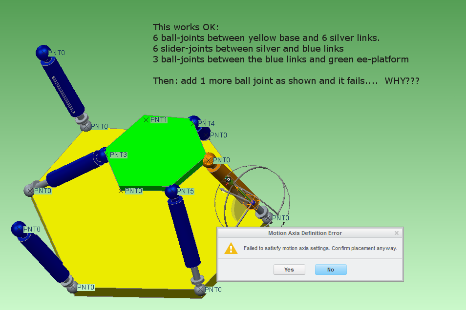
6DOF+platform+problem.png

What Creo magic am I missing here?

I notice that when I disable the "Allow regeneration values" on the slider joints, then I can assemble the green ee-platform to five out of the six blue links. The last one will look like it is assembled, but any dragging will automatically disable it. What gives? Because if this is indeed working as intended, then Solidworks is head and shoulders above it when it comes to assembly and movement of components.

Please try the model and help me. Is there some "assembly joint-satisfaction tolerance" setting that I should be relaxing?


This thread is inactive and closed by the PTC Community Management Team. If you would like to provide a reply and re-open this thread, please notify the moderator and reference the thread. You may also use "Start a topic" button to ask a new question. Please be sure to include what version of the PTC product you are using so another community member knowledgeable about your version may be able to assist.
Best answer by neomechanikos

Well, after playing with it, I got it to work. See attached. One minor problem is that the regen values that were initally set for the sliders might have been incompatible....they were all set for the same value but the hexagon platforms were not symmetrical so I just unchecked the regen value for the sliders.

The other problem I think has something to do with defining mechanism connections on both ends of the "links". Unfortunately, I don't know what the problem is or why it keeps disabling the last connection. I tried changing all of the ball connections to gimbal connections (hence the csys' that I added) to see if that would help but it still gave the same error and disabled the last connection. I also tried a mix of the two to no avail. You can switch them back to ball if you want.

Finally I tried changing all of the connections on the EE platform to simple coincident constraints and this did the trick. Again, no idea why your "ball connection" method and the gimball connection method I tried don't work and this "coincident" method does...essentially all three methods have the same degrees of freedom.

If anyone knows why changing the last connections to coincident constraints allows it to work, I'd love to hear it...

13 replies

1-Visitor
November 19, 2014

Well, after playing with it, I got it to work. See attached. One minor problem is that the regen values that were initally set for the sliders might have been incompatible....they were all set for the same value but the hexagon platforms were not symmetrical so I just unchecked the regen value for the sliders.

The other problem I think has something to do with defining mechanism connections on both ends of the "links". Unfortunately, I don't know what the problem is or why it keeps disabling the last connection. I tried changing all of the ball connections to gimbal connections (hence the csys' that I added) to see if that would help but it still gave the same error and disabled the last connection. I also tried a mix of the two to no avail. You can switch them back to ball if you want.

Finally I tried changing all of the connections on the EE platform to simple coincident constraints and this did the trick. Again, no idea why your "ball connection" method and the gimball connection method I tried don't work and this "coincident" method does...essentially all three methods have the same degrees of freedom.

If anyone knows why changing the last connections to coincident constraints allows it to work, I'd love to hear it...

psobejko1-VisitorAuthor
1-Visitor
November 19, 2014

I played around with the orignal ball-joint model and got it to work by relaxing the "relative assembly tolerance" under Model Properties. But that was not so good of a solution as the alignment was off considerably.

So thanks Eric for checking into this and teaching me a new trick. It's strange that simply changing the ball connections between the blue links and the green ee-platform to "coincident" type will fix the issue. You can then even go back and re-enable the regeneration values on the cylnder slider joints for all six legs and the model seems stable.

I think there is still the outstanding problem in that Creo will probably not achieve a good assembly if the cylinder lengths are prescribed. I am aware that the forward kinematics is a tricky math problem to find the hexapod ee_platform location and orientation from the six leg lengths (something like up to 40 "feasible" solutions, if I recall correctly). I think in Solidworks, you can get a "preview" of a possible ee-platform pose and the user is given the option to try to find another one. This way one can cycle through them and choose the desired one.

17-Peridot
November 19, 2014

More than once have I had trouble with the regen value checked.

Use snapshots instead to return to a known state. Regen after you reset the snapshot.

1-Visitor
February 26, 2015

Hey,

i got the solution of your mechanism...;

in that 1st you have to give 6 dof to ee (green) plate,

than cylinder to ball or gimble constraint...

here i attach the solution....

psobejko1-VisitorAuthor
1-Visitor
February 26, 2015

Interesting; thanks for the info. I'd love to examine the model but can't use rar.

Can you zip it instead?

1-Visitor
March 12, 2015

send me your email id, will send you mail....