
6-Contributor
July 10, 2026
Solved

CREO MDO for dyanamic balancing an internal combustion engine

  • July 10, 2026
  • 2 replies
  • 141 views

I have been using CREO MDO for some time to evaluate forces, crank torques etc. It works very well.


But what's the best way to dynamic balance a complex mechanism such as a internal combustion engine in MDO?
Best answer by tbraxton

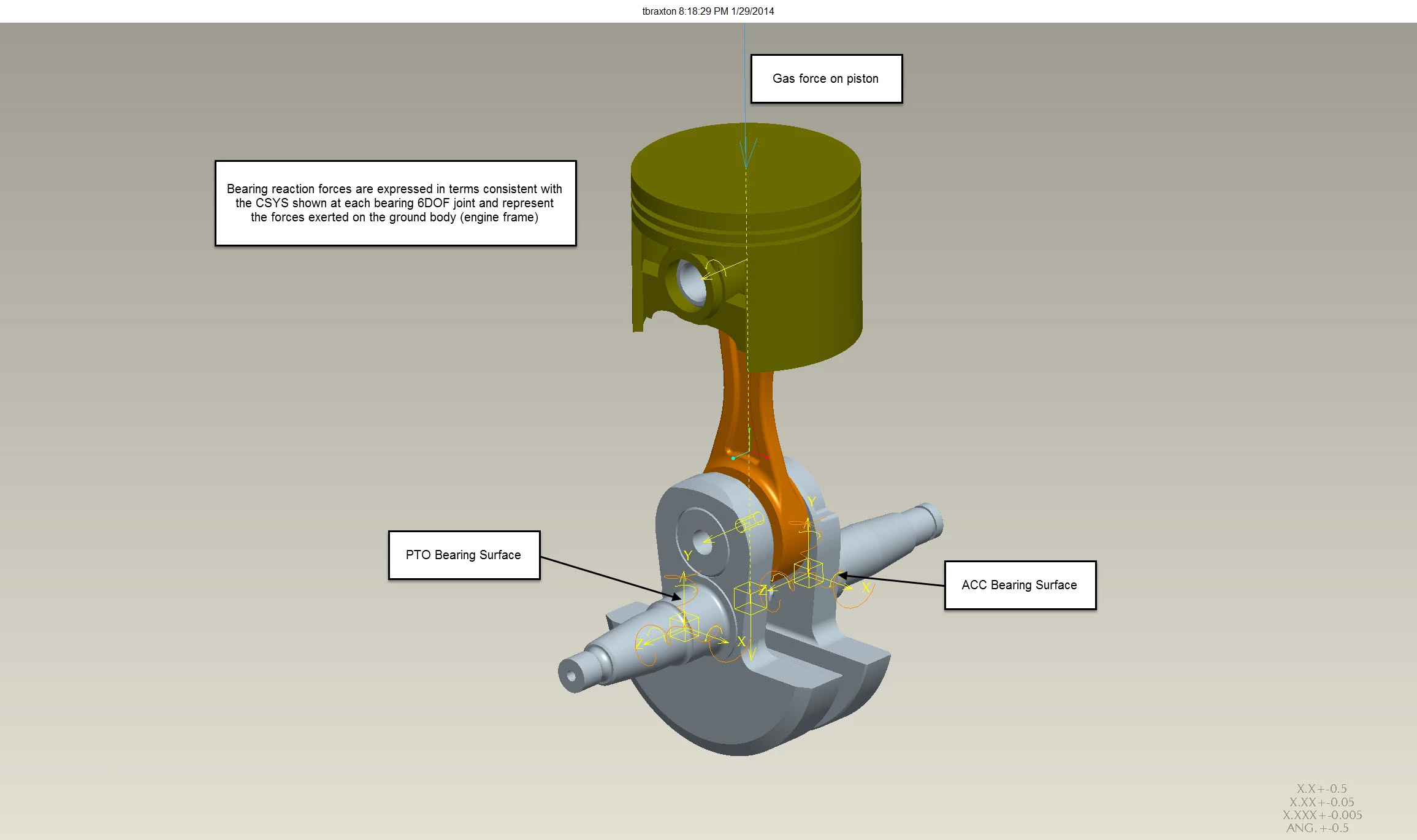
Here is an illustration of how to constrain the bearing supports locations of a crankshaft to the ground body using a 6DOF connection such that you can output the reaction forces (bearing loads) when using MDX dynamic simulation run. This is a construct that enables the extraction of the reaction forces at the bearing support locations. You are defining the joint so that all 6DOF are tracked during the dynamic sim enabling the calculation and reporting of the forces/moments in that connection.  I think that PTC has added a “bearing” joint that may replace this approach, but I am not positive. I have always used the 6 DOF joint definitions to get bearing loads.


Details on the 6DOF connection: Components for 6DOF Connection Reaction Measures


Check this out for bearing joint reference: Components for Bearing Connection Reaction Measures


2 replies

tbraxton
22-Sapphire II
July 10, 2026

The most effective method to “balance” the system is to employ Creo Parametric Behavioral Modeling Extension (BMX) to perform feasibility and optimization studies on your MDO simulation models. In some cases, you can perform this on an individual part (i.e. rotating crankshaft) and for other you will need to minimize the shake forces on drivetrain components in a more complex MDO simulation where you are minimizing the shake forces measured at the bearings for example.

BMX will vary the parameters of model(s) while iteratively analyzing the output of the MDO analysis and rerunning the MDO simulation until a goal is met or no solution is found based on the bounded solution space.

See a simple example from of how this works: 


tbraxton
tbraxton22-Sapphire IIAnswer
22-Sapphire II
October 4, 2026

Here is an illustration of how to constrain the bearing supports locations of a crankshaft to the ground body using a 6DOF connection such that you can output the reaction forces (bearing loads) when using MDX dynamic simulation run. This is a construct that enables the extraction of the reaction forces at the bearing support locations. You are defining the joint so that all 6DOF are tracked during the dynamic sim enabling the calculation and reporting of the forces/moments in that connection.  I think that PTC has added a “bearing” joint that may replace this approach, but I am not positive. I have always used the 6 DOF joint definitions to get bearing loads.


Details on the 6DOF connection: Components for 6DOF Connection Reaction Measures


Check this out for bearing joint reference: Components for Bearing Connection Reaction Measures