

Did you know about custom free face
The datum plane FREE_FACE is the default plane for the creation of the electrode base. The datum plane is defined in operation UI and has an offset from the bounding box of the workpiece in +Z direction. The datum plane is copied into every new electrode and therefore all electrodes have the same height over the workpiece if the automatic processing is used:
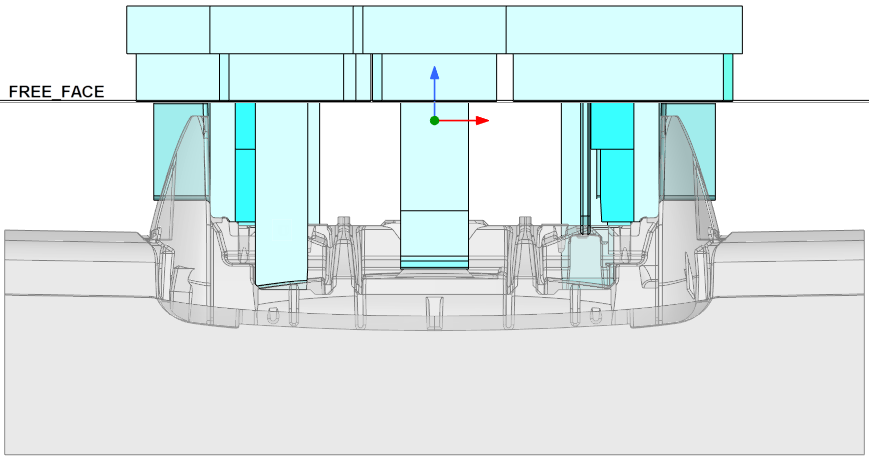
For the highlighted electrode it makes sense to place the base deeper in the workpiece to minimize the required size of the blank:
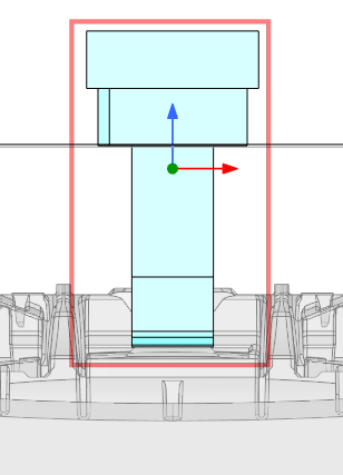
This can be done in two different ways:
Redefine datum plane FREE_FACE in electrode
| 1. | Select FREE_FACE and start redefinition | 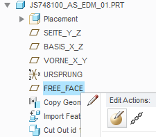 |
| 2. |
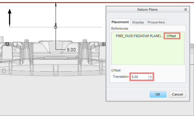
Change constraint type from Through to Offset and edit translation value Confirm feature definition |
 |
| 3. | Result | 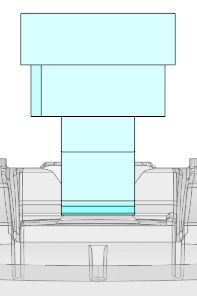 |
Note
FREE_FACE is still dependent from assembly default and adopts all changes accordingly.
Create base on selected surface
In the second approach, the surface for the base will be selected by user during the electrode design.
| 1. | Extract and cleanup electrode geometry | 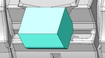 |
| 2. | Design offset | 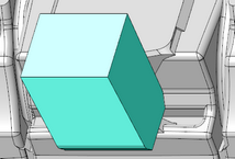 |
| 3. | Select surface for base creation | 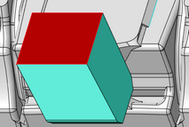 |
| 4. | Add base |  |
| 5. | Result | 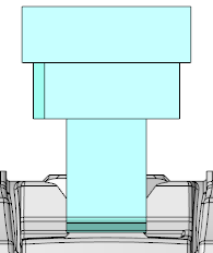 |
This thread is inactive and closed by the PTC Community Management Team. If you would like to provide a reply and re-open this thread, please notify the moderator and reference the thread. You may also use "Start a topic" button to ask a new question. Please be sure to include what version of the PTC product you are using so another community member knowledgeable about your version may be able to assist.