

Solved
Align wires when drawing in Creo Schematics (pics added)
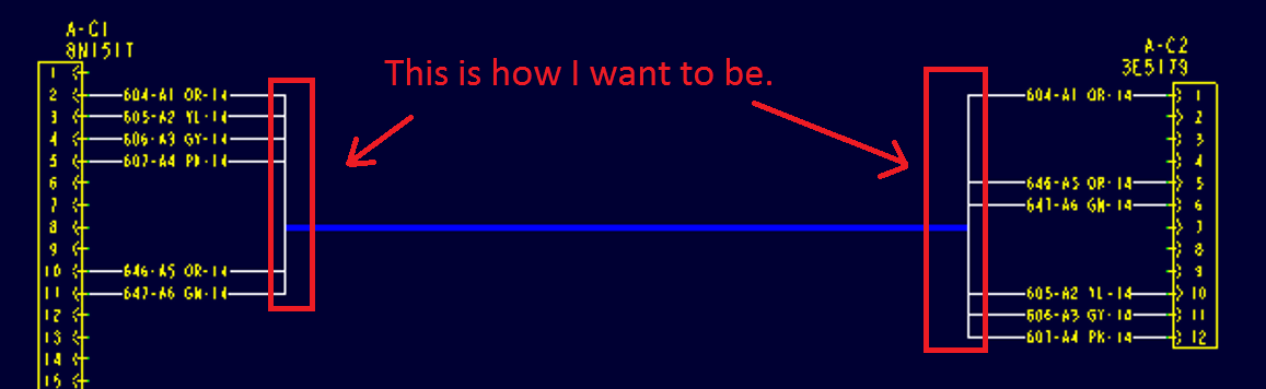
Hello, I need a help by drawing wires between connectors, when I want to draw harness in Creo Schematics 2 (lite ver.). I added two pictures - one is drawn by me and the other one I got from one powerpoint presentation named Routed Systems.ppt from internet where you can see how I would like to see aligned wires in to one highway. I drew in Diag Type: Wiring and wires label position is set to Both Ends.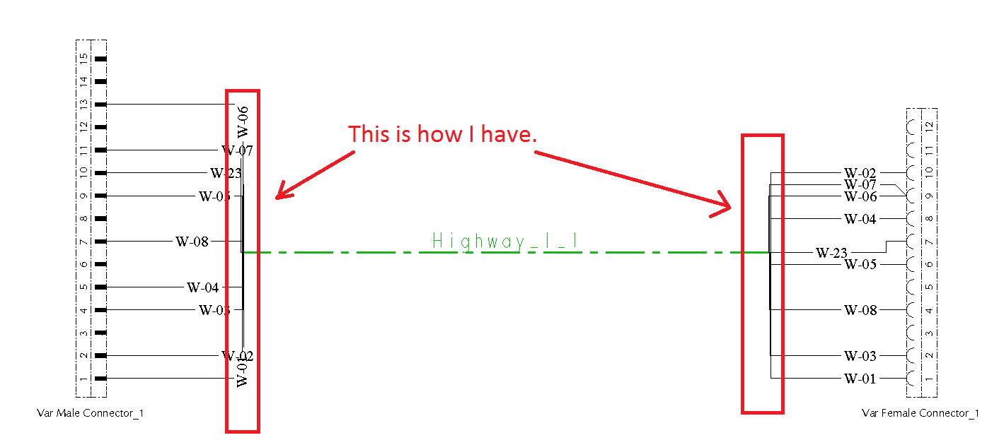
Thanks in advance for your suggestions and solutions.
This thread is inactive and closed by the PTC Community Management Team. If you would like to provide a reply and re-open this thread, please notify the moderator and reference the thread. You may also use "Start a topic" button to ask a new question. Please be sure to include what version of the PTC product you are using so another community member knowledgeable about your version may be able to assist.