1-Visitor
July 22, 2022
Solved

Bug related to Assembly Reference Pattern Both and pattern tables Creo 6.0

  • July 22, 2022
  • 1 reply
  • 4018 views


I have 16 years experience with ProE release 20 (~from 1999). My company recently upgraded to Creo 6.0, a big jump yes.


I've been doing assembly reference pattern both for 15 years and now there is a bug.  It works great in ProE release 20, but not in Creo 6.0


I did find this thread which may be the same issue, but not much else. 


https://community.ptc.com/t5/3D-Part-Assembly-Design/Components-missing-in-reference-pattern-both/m-p/561184


From what I can tell the bug is released to pattern tables. In the case of dimension patterns, the reference pattern both works great.  I used dim pattern on  planes, and then a dim pattern that was reference patterned to the planes. (pattern of a pattern)
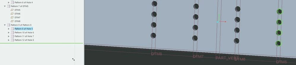
 

ScreenShot2025.jpg


Then for the assembly, when reference pattern type both is selected for a washer coincident with the first axis, the dots look correct like this:
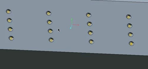
ScreenShot2026.jpg


and the washers come out correct:


ScreenShot2027.jpg


Okay, now under a very similar scenario, but the planes are a pattern table pattern instead of a dimension pattern.  It works great on the part.

 

ScreenShot2028.jpg


Then for the assembly, when reference pattern type both is selected for a washer coincident with the first axis, the dots look correct like this:
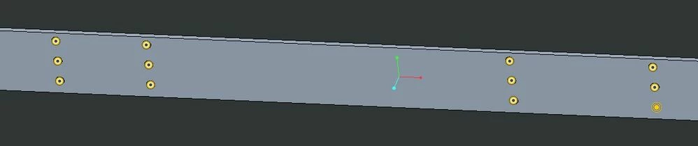
ScreenShot2029.jpg


But the washer pattern is not correct. The quantity is correct at 12, but the 4th,5th,6th items are all coincident with the first axis. This makes interferences and no hardware on the last 3 holes.  What gives?  This is definitely a bug. I tested in ProE release 20 and it does not do this. Has anybody else seen this?  Any thoughts, ideas?

 

ScreenShot2031.jpgScreenShot2032.jpgScreenShot2033.jpg


I also tested grouping the plane with the holes and doing a pattern table on that group. That works but I don't like doing this because you can't move things in/out of the group once patterned, so it is harder to maintain and work on. I like having a robust pattern table of planes by itself so the pattern doesn't need to be destroyed if I want to add/remove features. 


-JonA

Best answer by tbraxton


I am not sure it is a bug. I explain why below.

If you think it is then you can log a tech support call with PTC using this link.

https://support.ptc.com/apps/case_logger_viewer/cs/auth/ssl/log 


The documentation does indicate that the indices start from 1. Once you get past that the indices must be unique but not sequential. It comes from conventions used in programming (0,1,2....). This is displayed in the table editor and is in the help files.


  • From the header in the table editor:
  • Input placement dimensions and model name for each pattern member.
  • The model name is that of the pattern leader or any of its family table instances. Indices start from 1. Each index has to be unique, but not necessarily sequential.
  • Use for default value equal to the leader dimension and model name.
  • Rows beginning with ’(@)' will be saved as comments.


1 reply

tbraxton
22-Sapphire II
22-Sapphire II
July 26, 2022

I am not able to replicate the issue as presented in Creo 4 (m060) or Creo 7 (7.07). I do not have Creo 6 installed for testing. I have included a Creo 4 data set for testing. Inspect my version and confirm it is following the same model structure for the patterns. If not explain what the inconsistencies are and I will update the models on my end.


Open the assembly and test regeneration in Creo 6. It is possible it is an issue in Creo 6 but that would require some more testing.


When you did this in Creo 6 did you use a start part that was created in in Pro/E release 20? If so I would save a copy of that start part in Creo 6 and try this again. 


tbraxton_0-1658796630594.png


GMMCO1-VisitorAuthor
1-Visitor
July 26, 2022

tbraxton-

Thank you for taking the time to help me and try for yourself. You've helped me figure this out. 


I've discovered the source of the bug and a workaround. Unfortunately the work around will likely break many dimensions on drawings, exploded states, sections on drawings, etc. 


The bug comes from the first entered row of the pattern table.  Should the idx be 2 or 1?  I was always trained that it should be 2, because it is the 2nd thing. Accordingly I have hundreds of parts in my library like this.  


This:

ScreenShot2043.jpg


or This:

ScreenShot2042.jpg


When the first entered row starts with idx 2, I get the assy ref pattern both bug:

files attached.


ScreenShot2039.jpg


What's the generally accepted practice?  What is correct from PTC?  How can I let them know about this bug?


I'm not the only one who puts the first entered row as 2:


ScreenShot2041.jpg


19-Tanzanite
July 26, 2022

Well, I do see your point about the 2nd thing should have the index of 2.

On the other hand, this software was made by C programmers and so they count from 0, so the 2nd thing is at index 1.


And to be fair, the instruction was always there:

pausob_0-1658870168856.png