1-Visitor
February 26, 2015
Solved

Can't break dimensions outside view boundary... how to break manually?

  • February 26, 2015
  • 2 replies
  • 9829 views

Hey guys/gals,


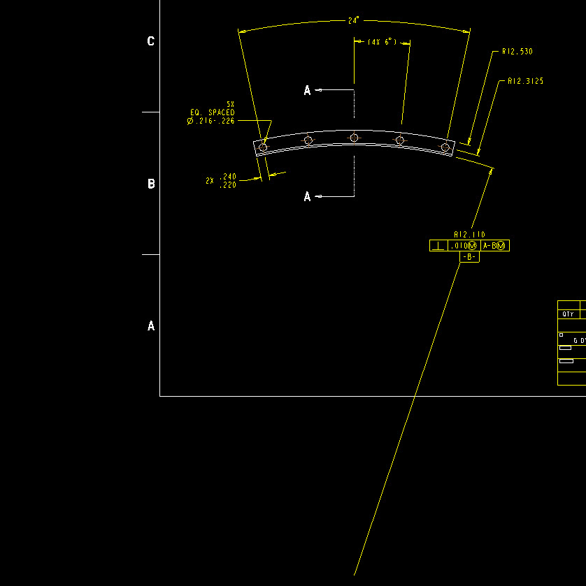
I have had this come up before on rare occasion, but now it is in front of me here in Creo 3 so I wanted to lob it out to you all.


The system is supposedly going to break dimensions for you, or foreshorten them, automatically based on the drawing view boundary and all that. Basically when the dimension falls outside the view box, it should just appear as a double arrow on one side indicating the clip. Well I believe I have all the drawing options on clipping set to yes in the detail config so this should work, however the dims pictures do not seem to observe this setting and I cannot find a way to break them on my own. It's possible I guess that all my previous experience is with linear dims and not radius stuff, but that seems like a poor limitation because round parts are more likely to have an axis well off the page anyways.. but whatever. I did try the help and seriously, the layout and usefulness of that is as badly formatted as this forum. Actually I will give this forum the nod on that because this week I've managed two threads in two tries, with the help, its zero for five.


Does anyone know how to force a break on stuff like this, or what click/pick/setting I am missing in this? The leader clearly leaves the drawing format and after all, we're on pro 34 here. The odds that I am the first one to cross this bridge are beyond lotto.


Please/thanks!!!


snap4279.jpg


This thread is inactive and closed by the PTC Community Management Team. If you would like to provide a reply and re-open this thread, please notify the moderator and reference the thread. You may also use "Start a topic" button to ask a new question. Please be sure to include what version of the PTC product you are using so another community member knowledgeable about your version may be able to assist.
Best answer by TomD.inPDX

There is a Z-radius option in the annotation dropdown under the dimension.

That is how you manage very large radii on drawings. However, it is not bug free as I have recently reported an issue still present in Creo 3.

good luck.

Creo Drawing....Cleanup Dimension Issues for diametrical dimensions

2 replies

14-Alexandrite
February 26, 2015

What are you showing in the picture is a radius dimension. The automatic dimension break works for linear and diameter dimensions.

For radius you need to use "Flip Arrow".

gdyal1-VisitorAuthor
1-Visitor
February 26, 2015

Yes sir, I agree there are several flip options available, but none will let me break the dimension, only convert it to what you see. There are two other radii called out there, two were flipped into leaders, the third was left as shown from center to illustrate this point. As I said, maybe I'm used to linear dims, but it sure seems plausible that a way exists to show an off screen axis without the leader streaking out of view like that.

I don't know if the ASME would agree or not, but personally I don't like putting datum letters on a dim whether its acceptable or not. I would prefer to show an axis with a B on it, and some squiggle line or broken whatever showing my dimension going between. Regardless of my preference though, I would still like to break this thing if its possible.

Thanks for the reply.

1-Visitor
June 17, 2015

I have a drawing where I 'broke' the main view. There is a radius vertex is in the left side of the broken view and the radius is in the right side of the view. The radius dimension will not foreshorten to line the arrow up on the actual radius, however ends at location off the part on the right. The horizontal dimensions did foreshorten correctly.

?? Creo 2, M100

Kathy

1-Visitor
June 18, 2015

Hi,

Could you post a picture?

1-Visitor
June 18, 2015

I am not able to for this particular drawing. I'll try to draw a similar case on my other Creo seat.