1-Visitor
November 17, 2010
Question

Drawing Entity Colours

  • November 17, 2010
  • 2 replies
  • 16809 views

Hi, I have recently been working with a company which use Inventor. They sent me across some drawings which were cosmetically superior (in my opinion of course) to mine. I would like to try and make mine a bit more like theirs. Below is a screen capture of what I'm talking about.

inventor.JPG

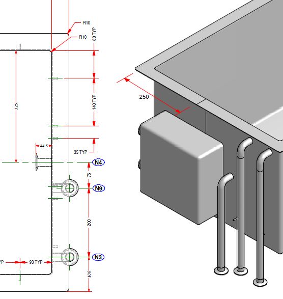
First up... how would I change my dimension leaders to red? I have tried editing my pen table file (pen 2 I believe?) but the colour doesn't change. Is there another way of achieving this?

Secondly, and I have requested this feature for years. I like the black lining around the shaded part, in drawing as well as in modelling mode. SolidWorks also does this. I think it makes it easier to see and visualise certain geometry.

Any feedback, comments or opinions?

Thanks

Lee


This thread is inactive and closed by the PTC Community Management Team. If you would like to provide a reply and re-open this thread, please notify the moderator and reference the thread. You may also use "Start a topic" button to ask a new question. Please be sure to include what version of the PTC product you are using so another community member knowledgeable about your version may be able to assist.

2 replies

1-Visitor
November 17, 2010

Hi Lee,

Double clicking on the dimension (or right click -properties in tree browser) will pop up one dialog which will give you option to change the text/leader color.

I dont think ( as per my knowledge) there is option to set black lining around the shaded part for drawing and for modelling.

Regards,

Niraj

LeeCasey1-VisitorAuthor
1-Visitor
November 17, 2010

Hi, thanks for the response.

Changing the colour in this way also changes the text to red, something I did not want to do. Also it is not very practical to do that every time I create a drawing. Can I assume there is an option in the config.pro for this? I would ideally like to change only the leader though and leave the text as it is. Anyone else have any suggestions?

Regarding the black outline, I think you are right, its not possible as I looked in to it a while ago.

Thanks,

Lee

24-Ruby III
November 18, 2010

Lee,

To print yellow witness lines in red colour, you can use the following pen definition

pen 4 color 1.0 0.0 0.0; thickness 0.01 cm; letter_color

To display part with coloured edges, you can use the following procedure:

set config.pro option option ... show_shaded_edges yes

assign black colour to whole part

assign grey colour to all part surfaces

Martin

1-Visitor
November 18, 2010

To have only red leaders on a screen drawing, in your Drawing Options file set


LINE_STYLE_STANDARD to std_iso


(this allows you to have different text and leader line styles)


Go to View>Display Settings>System Colors


Leader Color is controlled by Letter Color, so change it to RED

Text Color is controlled by High-Light Edge


Refresh the drawing.


The colors you get in the print are controlled by the *.pnt file - you will need to adjust them in that file if you want a colored print.


Heres a list of the various System Colors and the related drawing entity - whoever programmed this up was on planetPTC when they coded it - theres no rhyme or reason to any of it. Its taken hours to untangle the mess - hopefully its of some use to you. This had better not turn up in the new CREO.

!
! SYSTEM COLORS COLOR_NAME DRAWING ENTITY
! Geometry drawing_color outline geometry,section text/arrows
! Hidden Line half_tone_color hidden lines,datum axes/planes
! Sketch section_color sketch lines
! Curve datum curves
! Quilt quilt_color quilt edges
! Manuf Volume magenta_color quilt outlines
! Sheet Metal attention_color sheet metal
! Datum datum_color hidden lines,datum coords/axes/planes,datum tags
! Letter letter_color dim lines/leaders,gtol frames/leaders,
! hatching,threads,balloons & leaders,
! tables,surface finish,detail view boundaries,
! axes & centerlines
! Highlight-Primary highlite_color
! Highlight-Secondary dimmed_color tangent edges,section centerline,datum planes,coord x/y/z
! Highlight-Edge edge_highlite_color text in tables,balloons,details,notes,gtol,surface finishes

!
! Note
! LINE_STYLE_STANDARD affects text color as follows (it is set in the Drawing Options file)
! std_ansi - letter_color (detail view boundaries also altered)
! std_iso - edge_highlite_color
! std_jis - edge_highlite_color
! std_din - edge_highlite_color
LeeCasey1-VisitorAuthor
1-Visitor
November 18, 2010

Hi thanks for the information. However, I do not find the LINE_STYLE_STANDARD option in the drawings option file. I added it manually but it doesn't appear to do anything. I changed Leter color to red, this changes leader lines and text to red. I changed High-light edge to black but nothing happens. The text stays red. I'm guess this is what the LINE_STYLE_STANDARD configuration option is for but it doesn't seem to work for me? (using WF5).

1-Visitor
November 18, 2010

LINE_STYLE_STANDARD doesnt appear because youre using your standard drawing options file and it doesnt contain it. When you open an old drawing you need to refresh it so the new Drawing Options file gets used - otherwise it just uses the imbedded old options. This works in WF4 and WF5.

To refresh go Update Current Sheet(s)