
6-Contributor
June 29, 2018
Question

Family Tables and Threaded Holes

  • June 29, 2018
  • 5 replies
  • 7801 views

Is it possible to vary a tapped hole size in a family table?


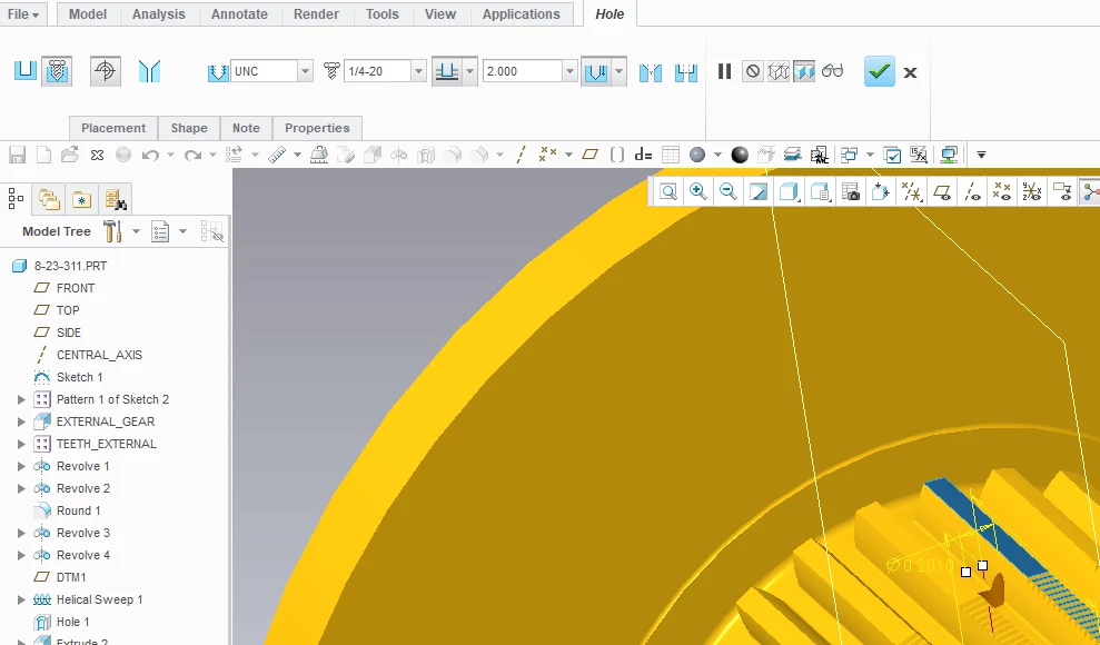
I have a family table of a hub where the key size varies by F.T. instance.  A tapped hole for a set screw over the key also varies based on key size. 
 

Kimble_27Jun.png


If I define a standard tapped hole, is it possible to change the thread in the family table?  (i.e. if the Generic has a 1/4-20 thread, can I have an instance with a 3/8-16 thread?)


Thanks!


5 replies

23-Emerald III
June 29, 2018

Yes, but it adds complexity to the table.

You need to have all of the tapped holes added to the generic and then add the features to the table and turn them on and off depending on which size you want in that generic.

Probably could do a more automated method with Pro/Program, too.

1-Visitor
August 14, 2018

Pretty much as was said in the previous answer.


Hole tables are not the same as family tables, though you would think that they should be. Therefore it isn't possible to swap out like features and components do in FT.  If you have 2 hole options then you need to model the two hole sizes in as 2 features and suppress the one that you don't want in the family table of the part. Make sure that you don't use the reference for the first hole as that for the second or they will both disappear when you suppress the first one.


Hope this helps.

slapha
15-Moonstone
March 20, 2019

Just a thought I had, no idea if it would work.

What if you made a UDF of the threaded hole, then varied the UDF with the family table?

It would be a bit of work to set up but it might work.


12-Amethyst
March 21, 2019

You could take your UDF idea a little further and create a UDF Family Table of your hub, key, tapped hole, everything.

10-Marble
July 13, 2021

I would like to have a folder of thread UDFs representing each size thread...2-56, 4-40, 6-32, etc. Each UDF would be table driven and the columns would be the parameters from the hole charts. The parameters I would like to vary are the minor diameter, thread depth, drill depth, drill diameter, drill tip angle, csink dia, and csink angle as depending on how you will machine the threaded hole will effect those parameters. My problem is when I use the UDF and select the instance, the holes always come out the same size...am thinking it has to do with the thread hole parameters being locked...is there a way to unlock them? in the udf or the hole chart? Would also like to have a UDF family table with nested family tables...is that even possible?

Chris3
21-Topaz I
July 19, 2021

There is no way to do this with the standard hole features. As someone else was suggesting above, you could create your own custom threaded hole feature (Helical sweep) and then vary the parameters of that feature. Obviously if you do this you loose the notes that are generated from the hole features. You also loose the ability to create a hole table based off of hole features (although depending on your requirements you might be able to use axes or points instead).

Patriot_1776
22-Sapphire II
July 19, 2021

There are parameters associated with the hole features.  I believe some of those drive the geometry, and some are driven by the geometry.  I have played with the parameters only in the dwg, as I've never had a need to switch hole size via a family table.  You might try digging into the parameters and see if you can add those parameters to your family table to get what you want.

10-Marble
July 19, 2021

I was able to add the parameters of the hole (derived from the hole chart) to the family table but when I selected the specific instance, the hole dimensions reflected the generic values...the hole is the same size regardless of which instance. When I went to Tools-parameters-feature and selected the hole, I noticed the access value is set to locked...could that be it? If so, how do you unlock the parameters?


Patriot_1776
22-Sapphire II
July 20, 2021

If they're locked, that means they are either driven by the geometry, or are locked via a relation (or locked deep in the software where you can't get to them).  I'm betting they're locked because they're driven.  I don't play with the holes much, but thought I remembered some being driving parameters and some being driven parameters.  I just couldn't remember which.  I don't use the "note" that Creo provides for holes because it doesn't follow ASME convention (SRSLY PTC?), so, my note used a combination of the dimension diameter of the thread and the parameters, using the ":att_feat" functionality since it seems to work pretty well now (didn't used to).  So, a combination of actual dimension and parameters might work for you.  See if these files help.