12-Amethyst
May 22, 2015
Question

Fasteners references edges definition error

  • May 22, 2015
  • 2 replies
  • 5901 views

Hallo,

I have a problem with defining fasteners idealization in Simulate (Creo 2.0 M110).

I have to define a fastener between two components, when I select the two corresponding edges, this error message appears:

1.png

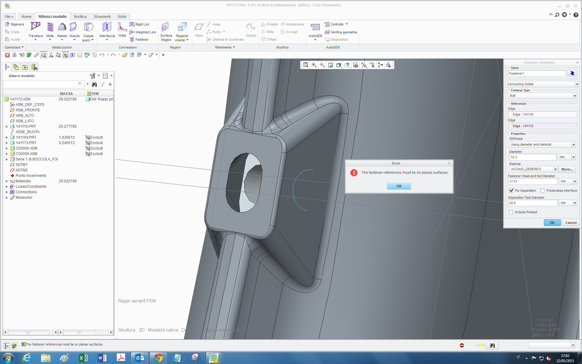
I suppose this errror is due to the fact that those are planar (in the sense that lie on a plane) but the visible one is not on a surface, but it's the end edge of the bolt hole:

2.png

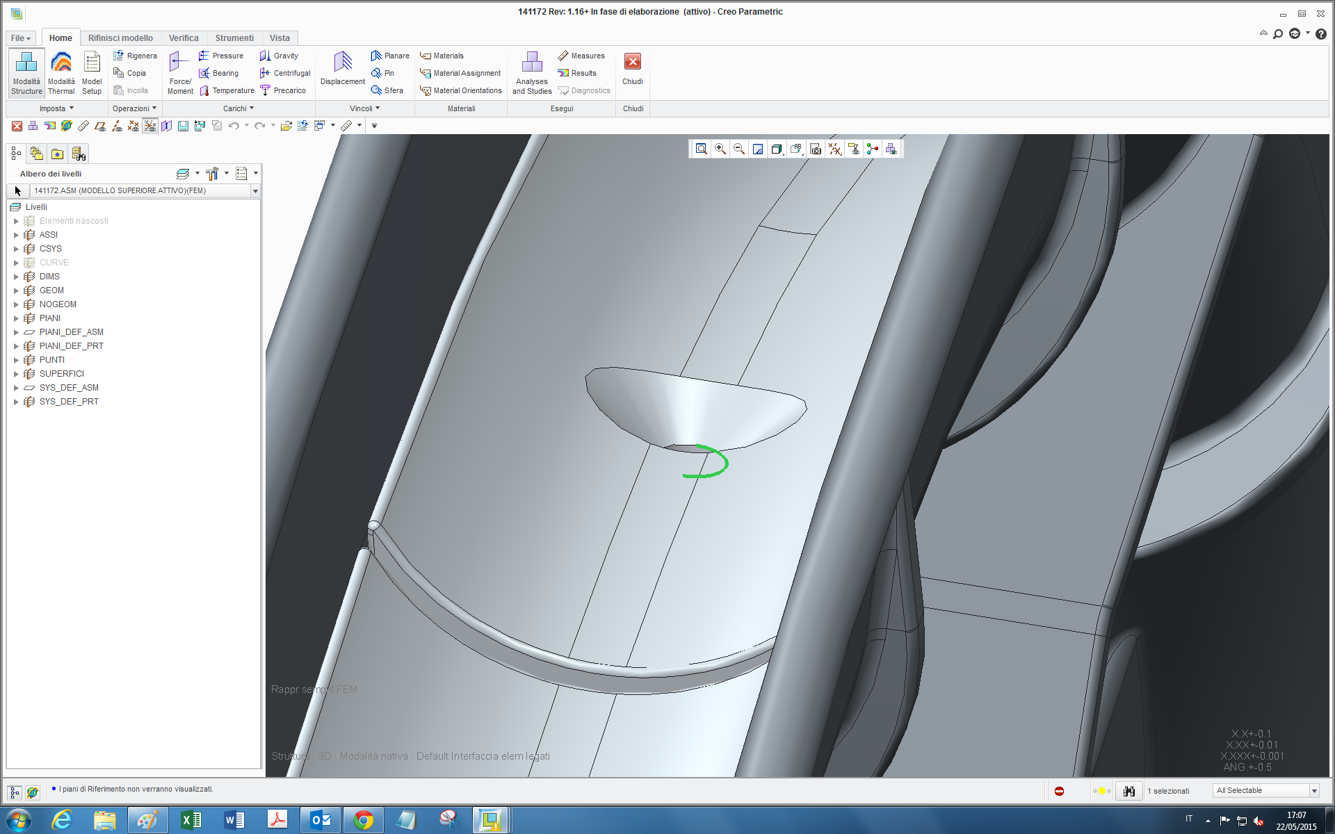
the question is, can I define in some way an idealized bolt for this case without having to add material (otherwise it would be convenient to directly add the bolt itself)?

thanks

bye

2 replies

1-Visitor
May 22, 2015

Tommaso,

Try adding a surface region or volume region where the fastener bounderies are.  This will give you a valid flat edge / line on the cylinder surface to select.

Hope this helps
Don Anderson

tleati12-AmethystAuthor
12-Amethyst
May 26, 2015

Hi Don,

I tried with a surface region in simulate but it can be created only on already-existing surfaces. In paametric instead, if I create a surface just inside the edge, in simulate it is not recognized and the error message still appears. With a volume region how can I do then to define the bolt?

thanks

bye

1-Visitor
May 26, 2015

Tommaso,

I was incorrect, you can use my approach for the end of the screw but not for the head.
You will need to use Mats suggestion or model the fastener as a solid and use the preload feature.

Don

1-Visitor
May 26, 2015

When I encounter problems like this I model the bolt using a beam element that I attach using  weighted or rigid links at the beam endpoints. Create a surface region for the bolt head/nut mating surface, as the independent side of the link. The pre-load i create using a zero coefficient of thermal expansion for "the rest" of the model. The bolt/screws are modeled with a large coefficient of thermal expansion. Then I prescribe a "-1 degree" global temp load. The bolts then contract. I can tune, either the coefficient of thermal expansion or the temp load to get the pre-load that I wan

Unfortunately beams can't be used in large deformation analysis, even though the beam itself does not undergo large deformations, other than "rigid" body motion.

tleati12-AmethystAuthor
12-Amethyst
May 27, 2015

Hi Mats,

thanks for the tips,how you define a beam? with a curve between the two points in parametric and then you define them as beams in simulate? or this can be done directly in simulate selecting the two points?

bye

1-Visitor
May 27, 2015

I typically create a point-point beam, from hole center to hole center. And yes, you can create the datum points in creo simulate, either on the top level, or on part level. If you create datum points on part level, in the creo simulate environment, the points end up as "Simulate features" in the model tree for that part, and are only visible in the simulate environment.

This technique is useful when the prerequisites for the "fastener" are not fulfilled, for example non-circular hole, or the surface might not be planar or parallel.

/Mats L/