1-Visitor
July 8, 2014
Question

How to move a leader from GTOL to dimension in a dwg

  • July 8, 2014
  • 3 replies
  • 10259 views

Hey all,

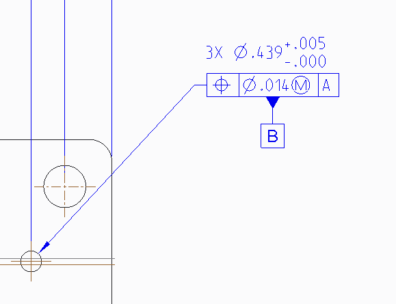
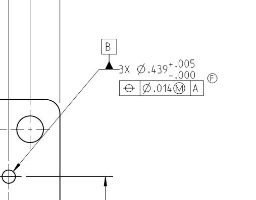
I am on Creo 2 and I am running into a problem where I am recreating a drawing and I can't seem to get the leader line to stick with the dimension, it always wants to go to the GTOL as soon as it is created. I beleive this is also the root cause to why I can't get my B datum in the right location.

I created the GTOL is a small assembly (2 pieces a base and weld nuts) then brought it into my drawing and regardless how many different ways I do it I still have the same result.

Any help would be appreciated!

Thanks

Sam


Before.png After.png

3 replies

17-Peridot
July 8, 2014

Hello Sam and welcome to the forum.

I share in your frustration. I just tried doing this exact thing and it wouldn't do it.

Really painful for something so basic and common.

The fact this is an assembly frustrates this even more.

I hope someone from PTC support will comment here with a "how too" best practices video.

Personally, I've had to give up on PTC's GD&T implementation.

17-Peridot
July 8, 2014

Creo, even in a part as ASME Y14.42 3D GD&T, is not allowing me to create the following example...

http://www.geotolmeadows.com/newsletters/2012/pic1.jpg

23-Emerald III
July 9, 2014

It can do that one. But don't get me wrong, I'm not defending it.

23-Emerald III
July 9, 2014

The problem is that PTC has a limited set of ways they do GD&T. When it comes to copying an old drawing or trying to make your GD&T look the way your company is used to seeing it, sometimes that conflicts with the limited ways that PTC offers.

I know Antonius got over the limitation by using symbols instead of the built in functionality. I got over also by accepting that sometimes I can't show it excatly how I want to show it but I choose one of PTCs limited ways and it is still fully to the standard and there is no chance for mis-interpretation.

Sorry it's not a real answer, but hopefully it will save you time and may give you a couple of ideas as to how to proceed.

Steve

Dale_Rosema
23-Emerald III
23-Emerald III
July 9, 2014

I am with Antonius. Symbolism over substance (that is not reliable).

23-Emerald III
July 9, 2014

That's funny, I didn't realize I had done it the way the original question was asking for.

I simply added the GDT frame to be attached to the dimension in the definition box.

gdt.jpg

I have never seen Creo allow you to attach the "B" datum to the leader of a dimension as show in the original image though.

1-Visitor
August 23, 2019

File --> Prepare --> Drawing Properties --> Detail Option

In "Option", Find for "gtol_datums" , Set Value as "std_asme"