August 22, 2016
Solved

Is there an automated way to toggle between constraint sets without using Family Tables?

  • August 22, 2016
  • 2 replies
  • 11096 views

Hello,

I have an assembly with a number of flip platforms. I have created them with pin connections and am using mechanism analyses to drive the assy into different configurations using servo motors on the pins. This works well as long as I am careful with the constraints so I don't lock up one or more of the connections.

These flip platforms also have guard rails and ladders that need to be installed or stored depending on the configuration. My current method is:

  1. Run the mechanism analysis for the desired configuration.
  2. Edit definition on all of the different guard rails and ladders and enable and disable the appropriate constraints.
  3. Update the snapshot of the individual configuration.

My model has grown more complex and step 2 is becoming quite tedious. I loathe family table assemblies and they are forbidden here as well, so I will not/ cannot use them. Is there something I can use in Mechanism, to switch between them?  I have tried using Rigid connections and was then hoping I could use the enable/disable connections constraint in Snapshot. 
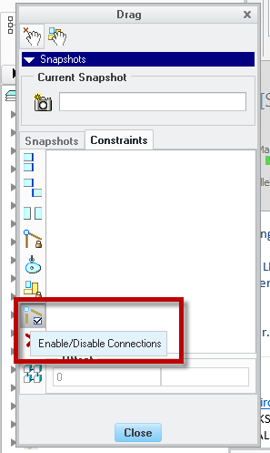
But the Rigid Constraints were not selectable when I tried that.

I would love it if there were something I could set up in my mechanism analysis that would work.


Thanks in advance,

Karl Krahmer

Best answer by TomU

Constraint sets can be controlled via simple relations.  I would suggest using a top level assembly parameter to determine which constraint set is currently active across each of the components.  Take a look at this article: https://support.ptc.com/appserver/cs/view/solution.jsp?n=CS46389  Let me know if you need help implementing it.

2 replies

TomU23-Emerald IVAnswer
23-Emerald IV
August 22, 2016

Constraint sets can be controlled via simple relations.  I would suggest using a top level assembly parameter to determine which constraint set is currently active across each of the components.  Take a look at this article: https://support.ptc.com/appserver/cs/view/solution.jsp?n=CS46389  Let me know if you need help implementing it.

August 24, 2016

Hi Tom,

   Thanks for the help.  This is very helpful. Just showing the constraint sets in the model tree is very helpful.  I am trying to write relations to drive the different states but I am having trouble with the syntax. I created a Yes/No parameter for my first constraint set and then added the constraint set from the list as shown in the link you provided. But it is telling me the relation has an error. I have tried with and without the quotes around the name of the constraint (which is "STORED").

/*SET CONSTRAINT SETS BASED ON PARAMETER VALUES

IF FSPAP_FLIP_EXTENDED== YES

PTC_CONSTRAINT_SET:FID_23684 = "STORED"

error Relation has an error.

Can you help me again?

23-Emerald IV
August 24, 2016

Quick guess without testing... try changing to PTC_CONSTRAINT_SET:CID_23684 = "STORED"  Constraints are part of the component (CID), not a feature (FID).

Let me know if that doesn't work and I'll do a quick test.

By the way, it might be simpler to place the relations in each component and simply reference the top level assembly YES/NO parameter.  That way the relations will be nearly identical for each component.

August 24, 2016

Thank you Tom and Paul!

I have been able to combine to motor driven mechanism analyses and constraint sets to get exactly what I need.

I created the top level assembly parameters as yes/no type that say what the overall state is.

I created component level IF relations to drive the appropriate constraint set based on the top level assy parameters.

Now I just set my top level assy parameter to the correct state and regenerate to move the components to their correct location.

Then I go into Mechanism and run the appropriate analysis. Then I open the Snapshots dialog box (drag components) and update the Snapshot for that state.

The total time is now down to 1-2 minutes from ~5-10 mins.

I might also be able to get rid of the mechanism portion altogether and not have to deal with the touchiness of Mechanism.

August 31, 2016

Ok, So I thought I would try to apply this technique throughout my assy and replace the finicky Motor Driven Analyses.

I can't seem to get sub assy level constraint sets to switch at the parent assy level. For instance, I have a hinge assy that I have 2 constraint sets defined with relations to drive them. I have made it flexible. But since the constraint set I am using in this assy is a bolted connection, that doesn't help.

I tried defining a subassy level parameter and use that to drive the constraint set. It works at the standalone level.

I made the subassy flexible and added the parameter to the flexible items. I  then added a relation to the parent assy to drive the subassy parameter (not optimum as if there were numerous instances of this assy, I may want them opened or closed independently).

The relation is:

IF FSPAP_FLIP_EXTENDED == YES

EXTENDED:FID_24412= "YES"

ELSE

EXTENDED:FID_24412= "NO"

ENDIF

And the parameter updates:

But the position of the hinge does not.

Can anyone help with why this is behaving this way?

1-Visitor
August 31, 2016

I'm not sure, but I found that when I wanted to write assembly or component level relations involving flexible components that go more than 1 level deep, then I had to use "associated parameters", which are parameters that are bound to the flexible component instance and available for controlling at the parent-assembly level.

Please read up on this, this is how they are defined (their access is hidden by default and a column needs to be added to the varied item table):

ASSOCIATED_PARAMETERS.png

So keeping the figure above in mind, suppose this MCMASTER_91290A318.PRT is being assembled and made flexible and ends up with FID of 24412.

Now suppose I want to change the value of the HARDNESS parameter for this component with an assembly level relation:  The code you listed is analogous to doing this:

HARDNESS:FID_24412 = "Rc60"

This would seem to be the logical way, and it would be accepted without immediate errors - but usually warnings about flexible var dims being re-set would start showing up in your message logs and you'd in general get weird results.

The correct way is to control the value of the HARDNESS parameter for this component by changing the value of the associated parameter "COMP1_HARDNESS":

COMP1_HARDNESS:FID_24412 = "Rc60"

That's the way I taught myself; I don't know why it works like that, but try and see if it works for you.