12-Amethyst
March 10, 2025
Solved

Model mill run-out for round

  • March 10, 2025
  • 4 replies
  • 1852 views

Using Creo 4.0 here ...

I have a 'handle type' part, that needs some edges rounded.

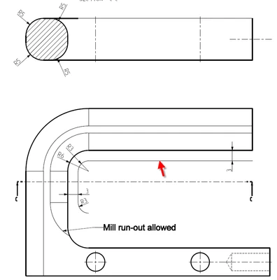
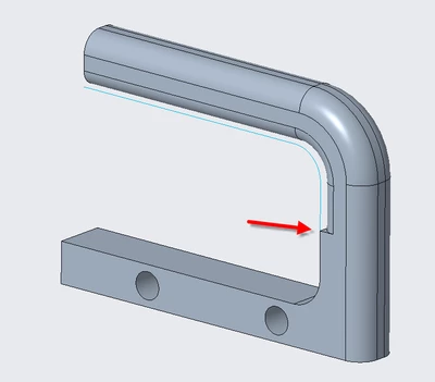
I have a problem with modelling the inner round because it has to stop 'halfway', where the red arrow is (see screenshot below).
If this part is produced on a milling machine, the round will of course not end 'abruptly' as shown below.

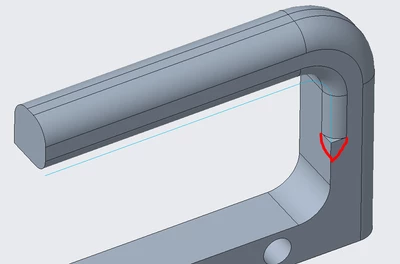
There will be some run-out of the radius mill.
How could I model this?
 

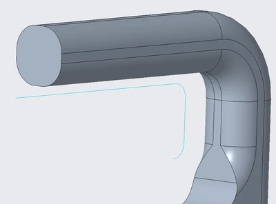
EddyVE_0-1741619052165.png

The inner round, I have now modelled as a sweep along a sketch (you can see the sketch as the blue line).


The mill run-out should look something like this:
EddyVE_1-1741619355970.png


Kind regards


Best answer by EddyVE

@StephenW @Patriot_1776 
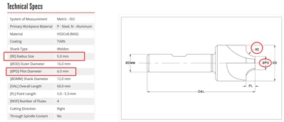
Ok, let's go that extra mile and look at an actual tool to produce the round and make the model accordingly.

EddyVE_2-1741638355596.png


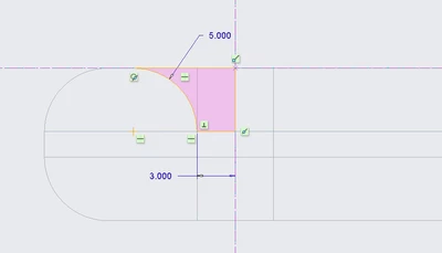
This is the matching sketch:

EddyVE_3-1741638439865.png

Note that the run-out (lead-out) radius can be larger than 3, but not smaller.


This is the sweep, modelled according the dimensions of the tool:

EddyVE_4-1741638481308.png

This is the result:

EddyVE_5-1741638521557.png


4 replies

KenFarley
21-Topaz II
March 10, 2025

For this kind of thing, to make the model look like what I'm going to make, I will add a revolved cut at end of the sweep. Revolve the shape of the cutter in the plane of the feature end. In addition to looking good, it's a pretty accurate representation of reality. A bit of work, but worth it.

13-Aquamarine
March 10, 2025

You can draw a curve on the side of the handle and then create a round using the "Thru Curve" option.

aputman_0-1741634103299.png


EddyVE12-AmethystAuthor
12-Amethyst
March 10, 2025

@KenFarley  and @aputman , you guys gave me just the push in the right direction that I needed.
The solution (or one of the multiple possibilities) was fairly simple. The sweep along the sketch that I already had, just needed a little tweak.
I added an arc at the end of the sketch to provide the run-out path of the milling tool. Now why hadn't I thought of that!


EddyVE_0-1741635005461.png

EddyVE_1-1741635069486.png


The sweep mirrored:

EddyVE_2-1741635117142.png


13-Aquamarine
March 10, 2025

That makes sense for something like a round-over bit on a router.  Glad you figured it out. 

EddyVE12-AmethystAuthorAnswer
12-Amethyst
March 10, 2025

@StephenW @Patriot_1776 
Ok, let's go that extra mile and look at an actual tool to produce the round and make the model accordingly.

EddyVE_2-1741638355596.png


This is the matching sketch:

EddyVE_3-1741638439865.png

Note that the run-out (lead-out) radius can be larger than 3, but not smaller.


This is the sweep, modelled according the dimensions of the tool:

EddyVE_4-1741638481308.png

This is the result:

EddyVE_5-1741638521557.png


23-Emerald III
March 10, 2025

Hahaha! I like it. I've used the term "Blend" to get something similar on drawing where I just needed a smooth transition out. 

But it's never a bad idea to understand the tools being used to do the job! 

Another option you possibly could have used is a variable radius, but honestly I think you developed a very good solution.