Motion skeleton - creating sketch rules
- February 23, 2017
- 4 replies
- 7715 views
Hello,
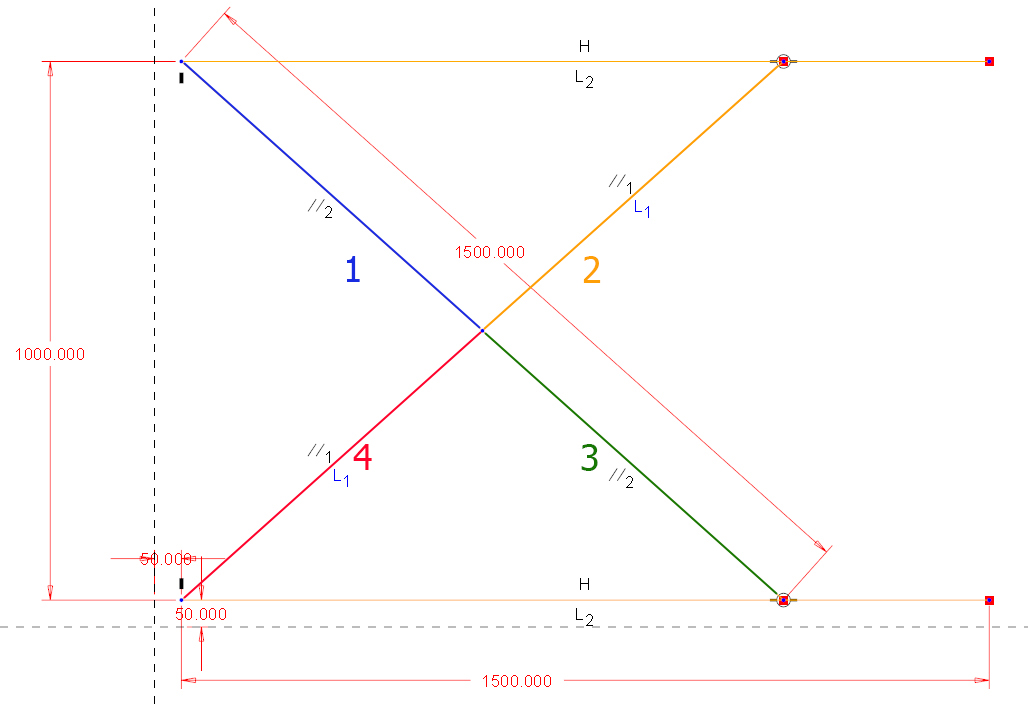
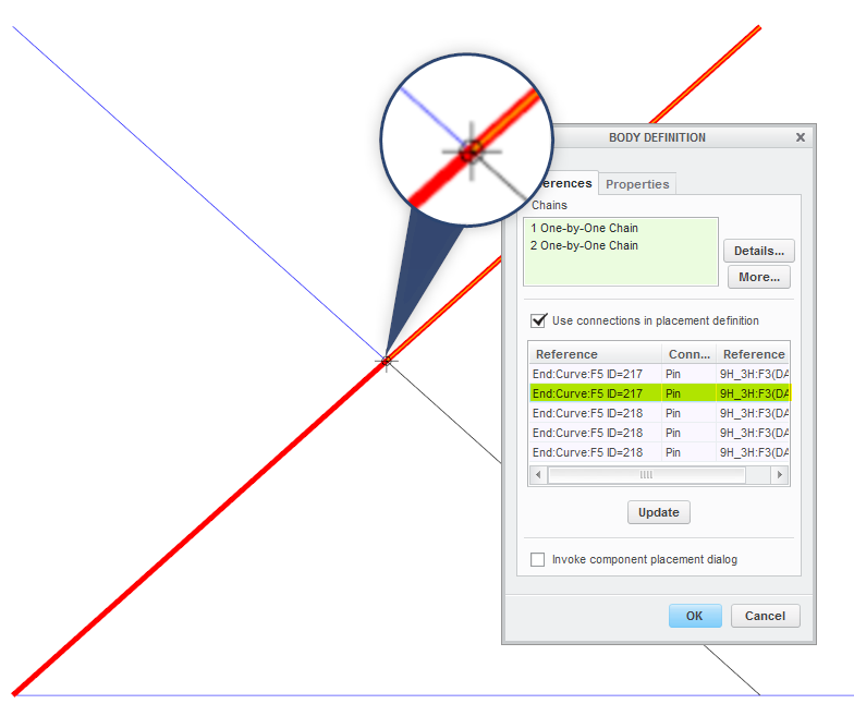
I want to use a motion skeleton in my design. I want to create mechanism like on the attached picture. I created body skeletons for all the bodies. GND, PART A, B, C. When I assign connection for body skeletons (In body definition dialog - not manually in component placement dialog) Creo doesn't recognise the mid pin. The two left PINs and Bearings are no problem but the center one. I tried to add circle to both PART A and PART B but unsuccessfull. I found in some training manual this:
After creating the motion skeleton assembly, you create a sketch. The sketch
must represent the following:
• The Ground Body – This is a non-moving component.
• Any Mechanism Bodies – Any moving part in the mechanism.
• Joint Connections, which are as follows:
– Pin joints can be defined at entity intersections or at circle centers.
– Slider joints can be defined from overlapping lines.
– Bearing joints can be defined where a line meets a non-endpoint location of another line.
– A Slot connection can be defined where a line endpoint lies on an arc or circle.
– Ball and Cylinder joints can be selected at locations where a Pin joint is found.
The entity intersection doesn't works, or I don't understand the meaning of this. Is there something else that it is need to take into acount when creating sketch (e.g.the order of creating sketch entities?). Could please someone explain the logic how creo look for connections between bodies?
thanks.