Pattern with fixed spacing but variable members extended till reference
Basically I am making grooves for a tiny coil of diameter like 0,5mm on a small cylinder body. I have made my 'groove', and revolved it around the axis of the cylinder and then patterned it using fixed spacing (pitch).
But I have to manually adjust the length of the cylinder body sketch to make sure it doesn't get interrupted.
Let me break it down to two objectives.
- I want the coil groove to be patterned automatically till a fixed reference edge/plane. The pattern cannot be interrupted midway unless it falls with 0.0Xmm of the seed pattern or 'whole'. (In other words, the last pattern cannot be broken or broken by a specified dimension 0,0Xmm. If it is broken then the wire diameter will not fit and that space is wasted.
- If this cannot be fulfilled, then the length of the cylinder is automatically reduced or increased to make that happen for the last pattern to be intersected by the given length 0.0xmm or be 'whole'/'undisturbed'.
I hope it is clear now. What is the best way to go about this? Table? The first objective if fulfilled, I can do the second point manually but it would be great if there is a way to do both.
Area fill pattern? But there is no area per se because my groove sketch revolves around the cylinder 360 degrees.
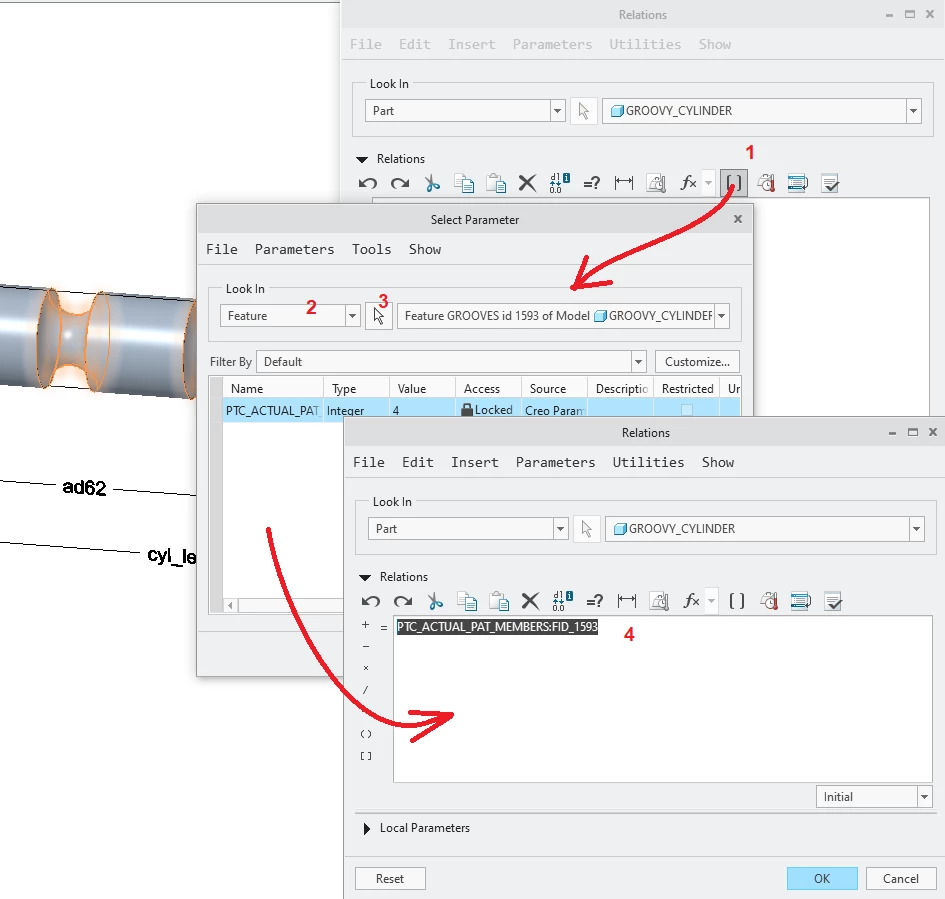
I don't see a way for the total 'whole' members to be determined automatically with fixed spacing because I have to define total number of members manually.
I am on CREO 10,0.7.0