
1-Visitor
May 16, 2014
Solved

Problem With Geometry? VSS Driven from Datum Graph

  • May 16, 2014
  • 9 replies
  • 3514 views

I needed a spring that I could use as a flexible component. It is a closed spring, so the pitch is different at the ends of the spring. I could have used the helical sweep tool, but I always fight with getting the variable pitch to work correctly and I wanted a bit more control. I decided to use a variable section sweep driven from a datum graph instead.

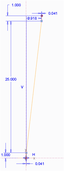
The datum graph that I used is shown below:
datum_graph.png

The X-Axis is distance along the spring, and the Y-Axis is number of turns. The spring that I am using is 3 inches in length, has a wire diameter of 0.041 inches and has 27 turns. The spring is closed so the first and last turn each use one wire diameter (0.041 inches) of the length of the spring, while the other 25 turns take up the rest of the spring's length (2.918 inches).

I create the foundation of the spring's geometry by sweeping a line around a trajectory. To spin the swept line around the trajectory I feed (trajpar * spring_length) into the datum graph to calculate what turn I am on, which I multiply by 360 degrees to get the angle of the line (which is sd5). The relation is shown below:

number_of_turns = evalgraph('SPRING_TURN_NUMBER', trajpar*spring_length)

sd5 = number_of_turns * 360

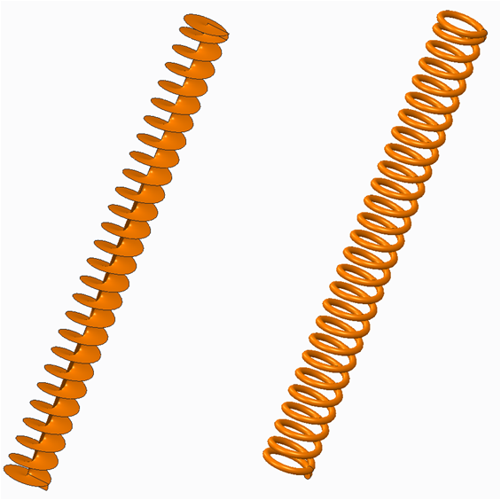
The result initially looks great (swept feature on left, and the final spring geometry on the right):
geometry.png

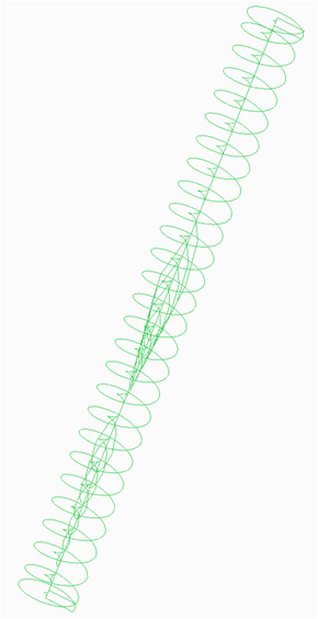
If I highlight the the swept surface (the image on the left above) I see some really funny stuff going on:
sketch_junk.png

Can anyone tell me what is going on here? The crazy going on along the axis of the spring shouldn't be there. Is this harmless visual junk that Creo is spitting out, or a symptom of an underlying problem with my relations in the Variable Section Sweep.

Any thoughts are much appreciated.

Edit: Re-Attached Broken Images


This thread is inactive and closed by the PTC Community Management Team. If you would like to provide a reply and re-open this thread, please notify the moderator and reference the thread. You may also use "Start a topic" button to ask a new question. Please be sure to include what version of the PTC product you are using so another community member knowledgeable about your version may be able to assist.
Best answer by TomD.inPDX

You might review this document and its comments: Closed and Ground Spring - Alternative to Helical Sweep

I ended up with a pretty good dynamic spring by using a wrapped sketch instead.

9 replies

1-Visitor
May 16, 2014

It looks like visual junk that Creo is creating when you select the object. I would start with looking at your model display settings. Maybe something in there will fix the issue. It could also be a graphics card issue. Of course it just may be that because of the way the part was made this is how Creo sees the part.

options.png

17-Peridot
May 18, 2014

You might review this document and its comments: Closed and Ground Spring - Alternative to Helical Sweep

I ended up with a pretty good dynamic spring by using a wrapped sketch instead.

17-Peridot
May 18, 2014

And the way you keep the VSS from creating the artifacts, try making the line you sweep only half the line as geometry, and the other (center) half construction; both equal lengths. That avoids creating geometry at the axis.

knorman1-VisitorAuthor
1-Visitor
May 19, 2014

This did the trick, thanks for the advice. I can now sleep at night

Also, thanks for referencing the spring document that shows the method using a wrapped sketch. I’m always hesitant wrap a sketch around a cylinder. Using Pi in one of the sketch’s dimensions that references the cylinder’s circumference worries me since I’m not clear on how Creo handles the small error with the rounding Pi. In the past, I have tried to wrap a sketch around a cylinder and Creo kept throwing an error. I was never able to complete the feature. I was convinced at the time that it had to do with the rounding of Pi but, who knows, it could have easily been an error with the user (and probably more likely).

I will recreate the spring using the wrapped sketch method to see how I like it. Maybe I can overcome my irrational (zing) delusions that using Pi to wrap a sketch around a cylinder is unstable due the rounding error in Pi.

knorman1-VisitorAuthor
1-Visitor
July 8, 2014

I know this thread has been dormant for a while, but I got distracted on a different project. I just came across some interesting behavior with the spring in when making a drawing (image that…) when creating a section view that I think is important to add to this thread.

There were two different methods for creating a spring shown in this thread:

  • My method of using a VSS driven from a datum graph
  • TomD’s method of using the wrap feature

I was able to model the spring using both techniques. Since I already had the spring modeled with my method in my assembly and correctly functioning as a flexible part, I decided to continue with my version of the spring. I needed to make a drawing of the assembly which required a section view. As it turns out, I couldn’t create the section view on the drawing. I kept getting: Cross-section created in view “new_view_#”, on sheet #, aborted.

When looking at the section view of the assembly in 3D, I found some interesting issues with the geometry with my version of the spring. Some of the ends were not capped.

cap_problem.png

I think this has something to do with the drawing section failure. I even tried to sweep a circular surface with the ends capped (making a hollow spring) and solidifying that part with no luck. I also found that importing spring geometry from a STEP file had this problem.

Springs modeled with the wrap feature don’t seem to have this section issue. Helical sweep parts are fine as well.

I can’t say that VSS springs will always have this problem, or that springs made with the wrap or helical sweep methods will always work (maybe someone here knows what is going on). I can say that I will be using the wrap method from here on out. In my limited spring modeling experience it is more stable and, and after a few times using it, more intuitive to use.

17-Peridot
July 8, 2014

I have been fighting this very problem all weekend long. Cross sections in Creo is as weak as it ever was. Mine is Creo 2.0 M040. Offset sections utterly failing and normal sections not capping properly. Just really poor performance on the part of PTC. And its always been this way!

You might try using an "offset" when you edit the section on the drawing if the section doesn't fail the drawing completely. Sometimes you just get some bits that have no hatch, and the section responds to the "offset" value. Don't ask me why. In the model, I have not found a way to resolve this.

Care to submit the part to PTC customer support for evaluation?

If you could create a support case and provide feedback here, that would be outstanding!

P.S. to get it to work in the drawing, an old trick with springs was to rotate them a little in the assembly model.

Pro|WorkAround^TM #934,498

knorman1-VisitorAuthor
1-Visitor
July 8, 2014

I'm running Creo 2.0 M080.

I did try "offsetting" the section plane in both directions, as well as trying different section plane orientations. No luck. Thanks for the other Pro|WorkAround tip though! I'm sure that it will come in handy in the future.

I've been disillusioned with customer support in the past, but I will submit the part and report my findings. In the mean time good luck with your cross sections!