

Sheetmetal Challenge
Let's see if a blog can get some discussion going.
We have recently been discussing sheetmetal capabilities and the conversion tool was brought up.
So I decided that it might be good to investigate how to make use of this tool.
The 1st advantage I saw was better corner control... or maybe more desirable options... which typically fail when making sheetmetal walls.
Then I tried to make the sheetmetal fold-out version of the 6 basic views by starting with a cube. Here is where the fun begins.
Go ahead; start with a solid model of a cube and convert it to sheetmetal.
See what you can do with this challenge and post what you learned.
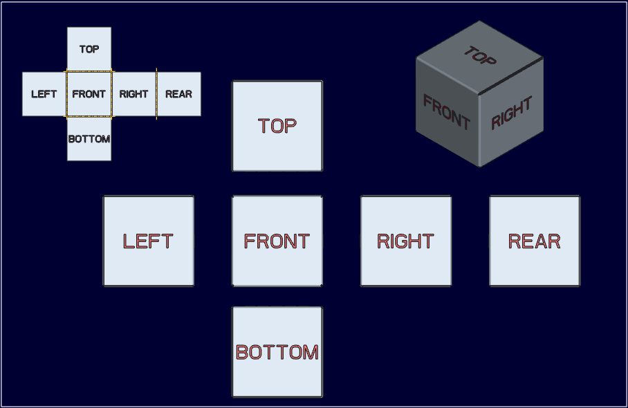
BTW: I use this as the default view creation model rather than using template models.
Edit: Since the original post was a tease, I figured I would update the post with more information.
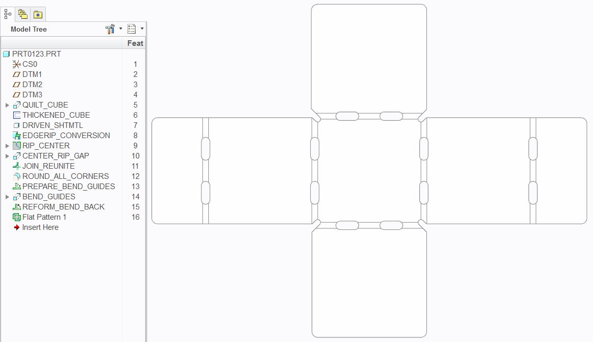
First of all, if you tried this, you might have noticed that a solid cube would simply flatten to the metal thickness when you define the sheetmetal conversion using the driven surface option, forcing you to use the shell option and loosing a complete wall. This didn't set well with me so I used the technique in the video: create the cube using a thickened quilt. Now the power of the conversion tool becomes apparent. The conversion tool has two levels, which is not immediately apparent. The rips can be treated individually and have a lot of power, many of which are particularly useful as it is difficult to re-create many of these when building a sheetmetal part from scratch. Between the rips and corner relief's, both of which were deployed in the attached Creo 2.0 file, you have nearly no limitation with a little imagination. The fact that you cannot create sketched rips inside the conversion tool had to be gotten around to divide the back wall down the middle. I am not sure there was an option to accomplish this otherwise. But the lesson learned here is that you must make a logical unfold part to get the corner relief's to work. Again, corner reliefs are more controllable in this conversion feature than they are on their own or in wall/flange features.
The cube in the video is a bit more practical as you cannot form a closed cube. The idea here is that this cube can be formed by hand (or at least with the use of a soft mallet).
Feel free to play with the model and change parameters. As always, use the information provided as you will.
This thread is inactive and closed by the PTC Community Management Team. If you would like to provide a reply and re-open this thread, please notify the moderator and reference the thread. You may also use "Start a topic" button to ask a new question. Please be sure to include what version of the PTC product you are using so another community member knowledgeable about your version may be able to assist.