
1-Visitor
April 25, 2013
Solved

Sheetmetal Difficulties - Can you figure it out?

  • April 25, 2013
  • 24 replies
  • 11301 views

Hello all,

I'm trying to recreate a part in Pro-E Wildfire 4.0. I've attached the .prt file that is from a step file. How can I make my own in pro-e using one piece of sheetmetal? I've tried just about everything but to no avail (deformation area, mirroring, solid-convert to sheetmetal, just sheetmetal, etc.). If you have some free time and would like to try and figure this out, please let me know how to do it! I'm stumped and very short on time with this project.

P.S. It has to be able to convert to a flat pattern so we can get this manufactured.

Thanks,

Sam


This thread is inactive and closed by the PTC Community Management Team. If you would like to provide a reply and re-open this thread, please notify the moderator and reference the thread. You may also use "Start a topic" button to ask a new question. Please be sure to include what version of the PTC product you are using so another community member knowledgeable about your version may be able to assist.
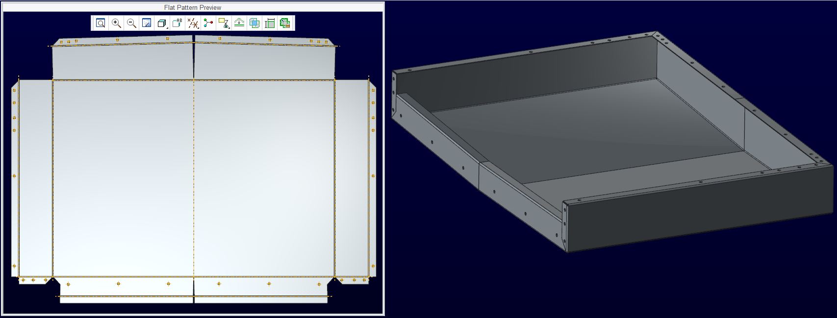
Best answer by TomD.inPDX

A good afternoon's excersize...

Roof_Panel.JPG

...and "The Movie":

Video Link : 3917

I must be getting better at the sheetmetal module. This was easier than anticipated.

I'm sure a few features could have been simplified but in all, 72 features with welds and unbend/rebend. Not too bad. Any sheetmetal poweruser tips welcome.

Creo 2.0 and STP attached:

24 replies

21-Topaz II
April 25, 2013

I would think this could be modeled as a solid with radii at the top edges and then converted to sheetmetal by shell. Then, add a conversion fearture to edge rip the sides. You'll need a very narrow cut down the one face from the shallow peak so it can unfold properly. Then you can add the walls needed for the bottom return flanges.

Good luck.

SamLamb1-VisitorAuthor
1-Visitor
April 25, 2013

Thanks Doug. By narrow cut, do you mean remove material by using extrude? Also, you're saying put the radius in the top edges of the peak before conversion? If I could just get the top and sides figured out, the bottom flanges would be a breeze.

21-Topaz II
April 25, 2013

The side that looks like one piece and has the peak at the top would have to be split in order to unfold. After converting to sheetmetal, yes, I think I'd create an extruded cut to remove that material.

17-Peridot
April 25, 2013

That almost looks like an outdoor utility enclosure roof.

You need to have one question answered by the fabricator. Is the center seam along the crown going to be welded and ground?

The way I see this modeled ...and fabricated, is to make the "kink" in the large top surface last creating a seam in the center of "front" and "back" flanges which will be welded and ground.

So what this means when modeling the part is that you need to account for the odd angles for all the bends. You can add the holes after you finish that shallow-angle bend in the top if that makes things easier. This should unfold without issues using this method.

17-Peridot
April 26, 2013

A good afternoon's excersize...

Roof_Panel.JPG

...and "The Movie":

Video Link : 3917

I must be getting better at the sheetmetal module. This was easier than anticipated.

I'm sure a few features could have been simplified but in all, 72 features with welds and unbend/rebend. Not too bad. Any sheetmetal poweruser tips welcome.

Creo 2.0 and STP attached:

SamLamb1-VisitorAuthor
1-Visitor
April 26, 2013

Wow thanks man! You make it look so easy. I'm comparing your step file as I'm making the part and I'm stuck at the 4th step where you make the 3rd wall. I just can't seem to match up with what you have for the relief on the left side. I'm guessing its a rectangular relief but I can get the wall to come out flush with the left wall. Any insight on how you did this? I bet this is a whole lot easier with Creo 2.0! Let me know if you get a chance.

Thanks,

Sam

SamLamb1-VisitorAuthor
1-Visitor
April 29, 2013

I got it figured out. The accuracy was the problem. What a eye opener that was! Thanks for all the help!

13-Aquamarine
April 29, 2013

Hi Sam...

Antonius' answer to this geometry is certainly valid. However, I'd encourage you to take another crack at the technique suggested by Doug Shaefer.

Hands down the best feature in sheetmetal is the Conversion feature. You can create most of the geometry you need for this model as a regular Creo solid that's been cut and shelled to the proper thickness. I haven't taken a very deep look at it... but I believe you can create this entire model with regular Creo features and less than 5 sheetmetal features.

I also think you can do it with better dimensional control in about half as many features. The Conversion feature is one of those best kept secrets that can really save you heartache when working with sheetmetal objects. Let me see if I can work up and example and post it.

I'm not saying Antonius' method is wrong. There's no doubt this technique works and uses pure sheetmetal functionality throughout. While I like working in sheetmetal, I find I like to use basic Creo modeling when I don't absolutely have to use sheetmetal. I have a similar philosophy for piping and cabling applications.

Good luck!

-Brian

17-Peridot
April 29, 2013

I have gone through that training module for the conversion before. It is indeed powerful. I suspect the corner reliefs would be easier too. Corner reliefs are the only real problem I run into using sheetmetal.

I reversed the process I used before by doing the 3 degree bend 1st, then using sketched flat walls. It made the whole process much simpler cutting the number of features in less than half.

I'm looking forward to seeing how you do the inward flanges using the solid shell, Brian.