
1-Visitor
September 1, 2014
Solved

Slanted fill pattern.

  • September 1, 2014
  • 3 replies
  • 5852 views

Dear community.

The company I work for hired a design firm to come up with some new design all our machines should follow. The problem is they came up with a design, we cannot make in a reasonable way in Creo.

The final product should look something like this:

F%C3%A6rdigt+m%C3%B8nster.png

The problem is, there's no option in fill pattern to do a slanted pattern.

The best way we have found to create the pattern is to make an oversized sketch pattern like so:
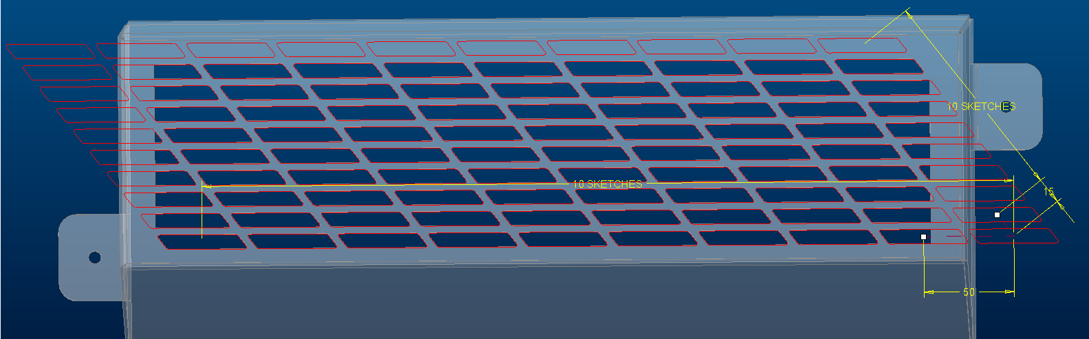
sketchpatt.png

We then make an extrude, where we project the sketches, that fit within the area we need the pattern like so:
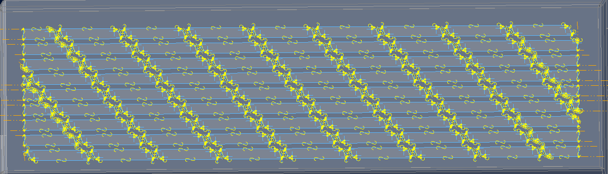
extrude.png

The problem we're facing is, that for every project you make in one feature, the slower the machine works.

It doesn't take long before the machine becomes completely unstable and crashes.

I hope you understand my problem, and that someone has a better way of doing this?

Please just ask if I haven't been clear enough in explaining the problem.

Thank you

Lars Kasch


This thread is inactive and closed by the PTC Community Management Team. If you would like to provide a reply and re-open this thread, please notify the moderator and reference the thread. You may also use "Start a topic" button to ask a new question. Please be sure to include what version of the PTC product you are using so another community member knowledgeable about your version may be able to assist.
Best answer by TomD.inPDX

We had a relatively involved discussion about complex pattern generation. The outcome was that Creo overhead in merging solids is excessive.

Feature Failure with Repeating Patterns

For your case, if this is a very common feature, I would almost entertain an import feature.

PTC did say they would think about expanding the fill pattern capabilities. I guess they didn't do this for Creo 3.0 (?). Being able to define the fill pattern geometry is almost obvious as a requirement.

I did find one method you might find useful if this is using sheetmetal:

  • Create the hole you want.
  • Create the --\-- FILL feature with fillets and all for each cell.
  • Pattern the fill feature as before
  • Merge all the fill patterns. Maybe a find will select them all quickly (?)
  • Extrude a surface to trim away the excess
  • Use an offset feature to solidify the grid

This removed 95% of the pattern regeneration overhead.

This again was much more challenging than it should have been. Way to many limitations in sheetmetal to make this intuitive. But I think this will solve your regen issue. How to "center" the pattern and managing master sketches is your second challenge. Finding a way to select all the merged surfaces easily is another challenge.

3 replies

13-Aquamarine
September 1, 2014

Just my initial thoughts...

You want these slanted features to be holes, correct?

How about:

  • Make a flat surface ('fill') somewhere outside your real part.
  • Create an 'oversize' pattern as you've already done, but extrude each parallelogram as a capped surface and merge it with the flat surface created above.
  • You should now have one quilt with lots of 'finger's sticking out of it.
  • Create a surface defining the outside profile of all the holes, un-capped and extending above and below the quilt created above.
  • Can you now merge this with the first quilt so that it still leaves a closed surface? If so, you should finally be able to solidify the quilt to cut the holes.

Good luck!

lkasch1-VisitorAuthor
1-Visitor
September 1, 2014

Hello Jonathan

Thank for the great idea, sadly I can't get program to merge with a pattern.

I tried deleting the pattern, and that made it possible to do the merge.

I then recreated the pattern and edited the merge, but it was still only the first instance that was merged, and it was not possible to add any of the other instances to the pattern.

I also tried to do a merge with one of the parralellograms that overlaps the edge of the border, here I get an error when trying to merge.

I hope I understood your suggestion right and followed it right, but I cannot get it working. Any other ideas will be greatly appreciated.

1-Visitor
September 1, 2014

Hello. Rather than create the slots, create the ribs, would that be easier? Would that even work? I can see what look like radii in the corners of the slots, so maybe not. It was just a thought.

John

lkasch1-VisitorAuthor
1-Visitor
September 1, 2014

Hey John.

It's worth a shot, but I can't really find a good way of sketching it, so I can pattern it. You're right there's rounds in the corners further complicating matters.

Thank you for the idea though.

17-Peridot
September 1, 2014

That is a lot of overhead on the system. I fully understand your seeking a more efficient method.

I am with John on this. Just use a big cutout and pattern --\-- and fill any remaining voids.

If this is a sheetmetal model, you can do this in the flat. That way you can manage any features that might just fall in the bend region. Often, sheetmetal has issues with this so learn the limitations.

1-Visitor
September 1, 2014

try like this

lkasch1-VisitorAuthor
1-Visitor
September 2, 2014

Hey Pepa Nos.

Thank you for your input, and making the video. Your sollution is actually how we make the oversized sketch pattern, the problem is just making the slanted pattern fit inside a box.