1-Visitor
February 25, 2014
Question

Solid "Deep Drawing" (how to?)

  • February 25, 2014
  • 4 replies
  • 15491 views

Hi all,

I modelled a flat "expanded metal" grid as a solid part:

expanded-metal-sample.jpg

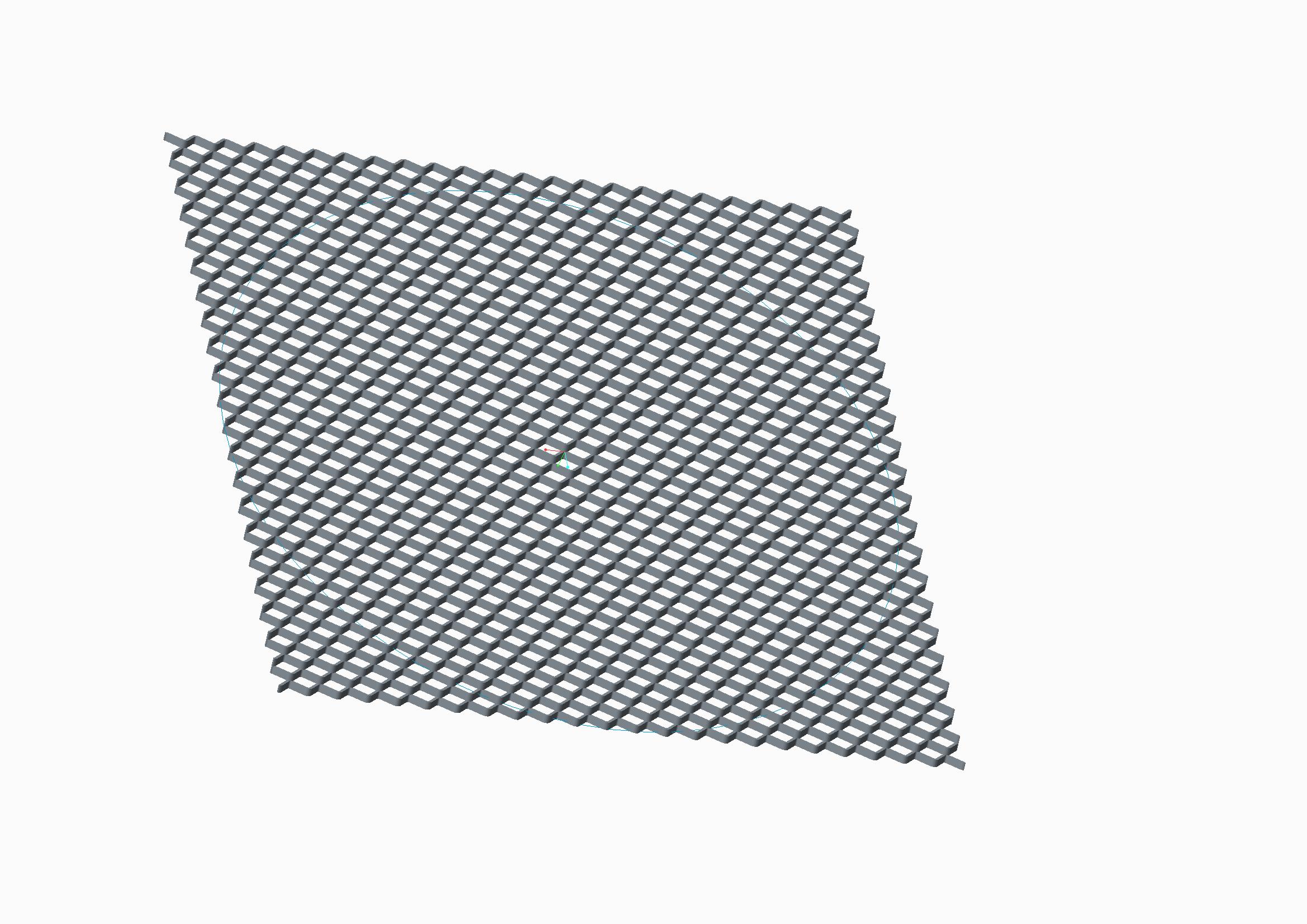
Now i would like to deep drawn it in order to give it this shape:

prova-bend.jpg

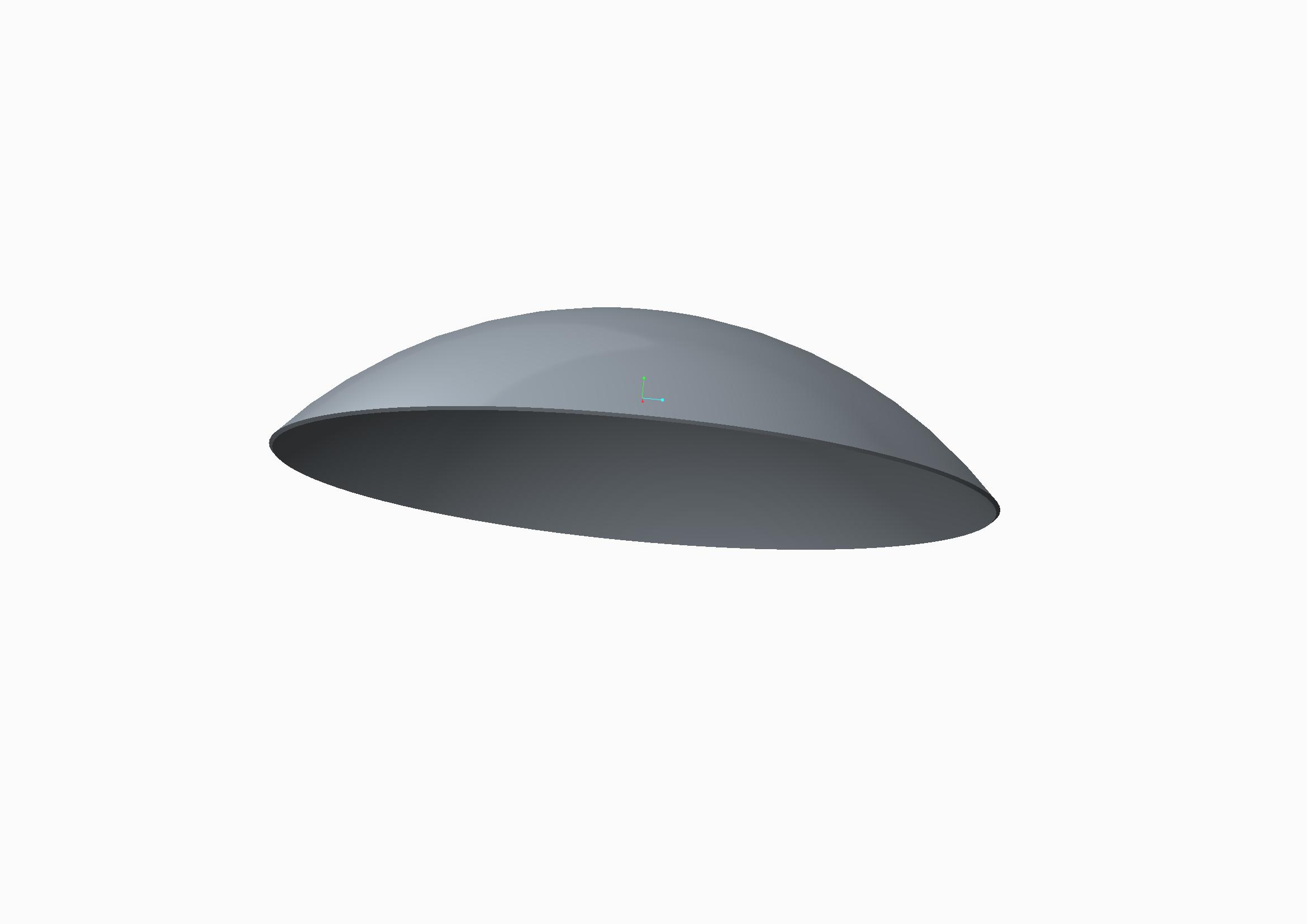
I already tryed the toroidal bend feature but I think I can only bend it around a trajectory (2D) and not deep drawn it (3D deformation).

I'm using Creo 2 Parametric

Any suggestion?

Thanks a lot


This thread is inactive and closed by the PTC Community Management Team. If you would like to provide a reply and re-open this thread, please notify the moderator and reference the thread. You may also use "Start a topic" button to ask a new question. Please be sure to include what version of the PTC product you are using so another community member knowledgeable about your version may be able to assist.

4 replies

17-Peridot
February 25, 2014

Welcome to the forum, davide.

You really know how to punish yourself. I don't know of any easy way to do this.

The closest I can think of to accomplish this is to creat a single cut feature and try to use a fill pattern.

This would be similar to a wire mesh screen formed into a dome.

here is a similar discussion:

Creating a wool-like fabric in creo 2.0

Patriot_1776
22-Sapphire II
February 25, 2014

Ummm, Toroidial bend MIGHT work, but. That looks to be a different type of "expanded metal" than I've ever seen. Most are 2D, with slits pulled open. That looks slit, but formed to be a 3D shape. THAT'S gonna be the difficult part. You MIGHT try it as a sheetmetal conversion, and then run it thru a form tool. Antonius is much better at sheetmetal than I so he'd really be the one to talk to.

17-Peridot
February 26, 2014

Here is one similar, Frank... often used for walkway treads.

http://www.traderscity.com/board/userpix43/28775-expanded-metal-stair-treads-2.jpg

Patriot_1776
22-Sapphire II
February 26, 2014

Hmmm, that is different. Interesting. The ones I've ever looked at closely were just flat. That makes it that much more dificult......and maybe fun?

1-Visitor
February 26, 2014

Thanks for your reply.

So I understand that Pro/E doesn't permit to lay (as a sheet) a solid geometry.

Regarding the suggestion to use Sheetmetal, I think it is not possible converting the original geometry because it hasn't a constant thisknes. See the image below:

expanded-metal-sample.jpg

The only feature I considered to use is Flatten Quilt / Flatten Quilt Deformation, but I think I cannot warp the geometry on a spherical surface (only cilindrical..)

Patriot_1776
22-Sapphire II
February 26, 2014

Try to convert it, what do you have to lose? The sheet it's made from IS a constant thickness, and remember that sheetmetal isn't going to see thickness as you do, I think it'll see it as being constant, which, in one way (the actual material thickness), it is.

Good luck!

17-Peridot
February 26, 2014

In sheetmetal, you need to be able to form it in two operations.

1st, the mesh itself uses the thickness as the narrow width of the section. The VVVVVVV shape for each course is a form; stepped for the second course, and if all works out, patterned. Then you would try a dome shaped form to dome the part. Then trim the diameter.

Can sheetmetal do this? Good question.

Patriot_1776
22-Sapphire II
March 3, 2014
17-Peridot
March 3, 2014

Oh, Frank... at least post us a picture and a synopsis

17-Peridot
March 3, 2014

Frank, your method is close and a lot more controllable than the Warp feature.

You can see that the edges still deform (the process is still X-Y "linear" rather than spherical).

In this case, I use a 10" disk, .1" thick wrapped on a 5" spherical radius. At the tighter bend, the difference becomes more notable. You can see the variation beyond the revolved cut.

However, with the revolved cut, you can definitely get this part a lot closer than the Warp feature does with a whole lot more control.

double_spinal_bend.PNG

Creo 2.0 full versioin attached.