

Solid Extrusions to Sheetmetal to Unbend
Hello, I am new to Creo and CAD in general. I work in fabrication mainly but am slowly learning various CAD and CAM systems. I am currently working on a project in Creo 7.0 where I am attempting to convert solid models into sheet metal parts with layout lines to be used in a CNC scribing and cutting operation.
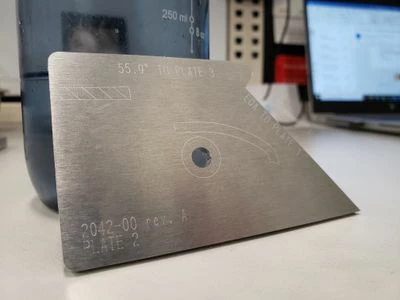
The end product is something like this, this particular component only has "flat" geometry so none of the following was required.
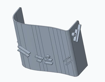
This is the part file I am starting with. The main plate is a sketched line that is extruded upward and outward to create the height and thickness. Then the smaller extrusions are sketched and extruded off of the main plate.
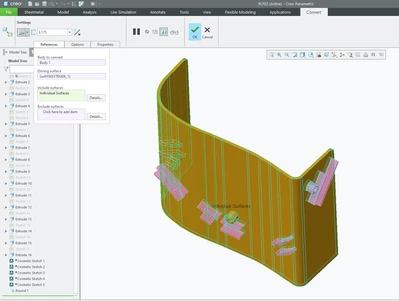
The following are steps I am taking to produce a usable view to cut on the CNC machine.
First, I am using the Convert to Sheet Metal tool. I select the flat surface on the right as the driving surface and add purple highlighted sections of the plate to the included surfaces so the whole plate is orange minus the small extrusions (if I add them the model will fail to regenerate).
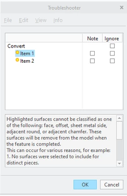
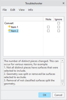
I then select OK and presented with these 2 errors.
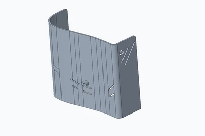
And the model begins to look like this with "holes" in it. And one extrusion on it because it would not allow me to remove it from included surfaces.
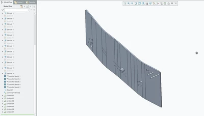
From here I begin to use the unbend tool individually on each curve. The "Flat Pattern" tool only results in a "fail to regenerate". Once un-bent it will look like this, not quite flat and has a part of the model out in space.
So, to me it seems like there has to be a more correct/easier way to do this. Is there a way I can take the face geometry of the surface with the extrusions and lay it flat? Once scribed and cut, the plates get formed into the shape of the original model and extrusions welded to the main plate. I am not the person who drew these models originally and we have 20 plus years' worth of similar models we would like to be able to convert like this. Thanks in advance, any help is appreciated.