

15-Moonstone
October 20, 2019
Question

toothed belt clamp

  • October 20, 2019
  • 2 replies
  • 2661 views

Hi,


I'd like to create a clamp that holds an toothed belt in place. Here you can see an example:
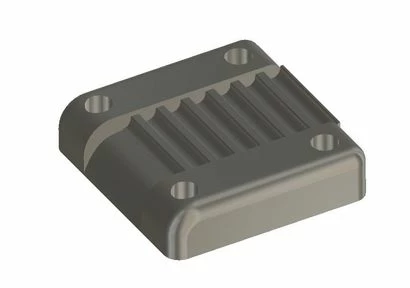
 

HTD-Halteplatte.JPG

I created this example using another CAD-System. Now I want to create the same (negative) HTD-5M-profile in Creo, with the difference, that the profile has to start at the beginning of the part.

I created my holding-plate and removed some material (using a spline and two straight lines):HTD-Halteplatte2.JPG
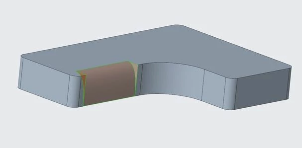
Then I created a sketch of the HTD-5M-belt, extruded it and patterned the extrusion along a curve. The result looks like this (with activtated sectional view):
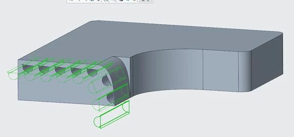
HTD-Halteplatte3.JPG


So something went wrong. Is this the right way to do it ? How would you do it ?


A sketch of the HTD-5M-Profile can be found here:

https://capolight.files.wordpress.com/2018/06/489bd-5m.jpg?w=640


Maybe someone can make a short video on how to do this ? 
Thanks,

Maik

2 replies

tbraxton
22-Sapphire II
22-Sapphire II
October 20, 2019

Your general approach seems valid. There are other options to get this done, design intent may come into play. Merge cut-out function could achieve this readily if you have a model of the belt already along the path. This would cut out the geometry of the belt from the block in a single feature.


If you would include your model or at least the details of the pattern leader including the sketch and the pattern properties that will help others figure this out.


It appears to me that your extruded cut for the tooth profile is not removing material from the clamp block. I can not tell why without seeing the sketch etc.

16-Pearl
October 21, 2019

yes, the pitch will change each time it travels over a curve. This works the same on the airport conveyor, some segments need to shrink when it turns. Not sure how you want it to be in this case.


In my model, I keep the sketched distance the same but it gets smaller after cut due to the overlapping of adjacent sections.

15-Moonstone
October 21, 2019

@BHOoi : 


Thanks. I think your solution is what I need.

I looked at your solution that looks very nice and have one question: why do you use two sketches in the group that is patterned ? Would it also work with one sketch only ?


I tried to create the part myself, but there is an error when I pattern the group. As long as the curve is a straight line everything works fine, but when the curve is bent then the sketches fail. So maybe i made a mistake in the sketch.


X1.JPGX2.JPGX3.JPGX4.JPG


Maybe you have an idea what i did wrong ?

Thanks,

Maik

16-Pearl
October 21, 2019

I tried and my model turned up like below:

belt.jpg


One thing to note is that the pitch might not be right at the corner area. I attached creo4 file here  hope it serves some help to you.


15-Moonstone
October 21, 2019

Hi,


Thanks for your replies.


@tbraxton: In BHOois-project you can find a sketch of the HTD-5M belt (and in my first post of this thread).


@BHOoi : That looks good, but the pitch is very important because the part is going to be manufactured and actually really clamps a belt.


And when I think about it: Doesn't the pitch of a belt get smaller when it its bend ? The tooth get closer to each other when the belt is bend. So maybe your solution is right ?


I also tried to do it with another technique. In my case the pitch seems to get larger.... You can see my approach in the file attatched.