
15-Moonstone
February 23, 2015
Question

Trying to set up relational table

  • February 23, 2015
  • 3 replies
  • 8172 views

I've never used Relation Tables before but I see where this might be quite helpful.

So far the only thing I've figured out is how to put in a text description in what I'd like the table to do.

I have a number of sections that I've made into a Swept Blend feature.

These sections need a modified draft value for the side walls.

For every section that I have (There are 14 total) I would like to increase the sidewall angle by 1 degree.

Since each section has 4 sidewall draft dimensions I will need 56 dimensions updated to increase the draft value by 1 degree.

I know that each dimension in the sections has a different symbolic name. Most of the dimensional values are different.

I'm thinking that I would have to modify the symbolic names so they include something in common, so the draft value will be changed in each of the 56 dimensions.

How would the relation table values appear for something like this?

To give you a better grasp of what I am working on I'll attach a snapshot of a few of the sections.
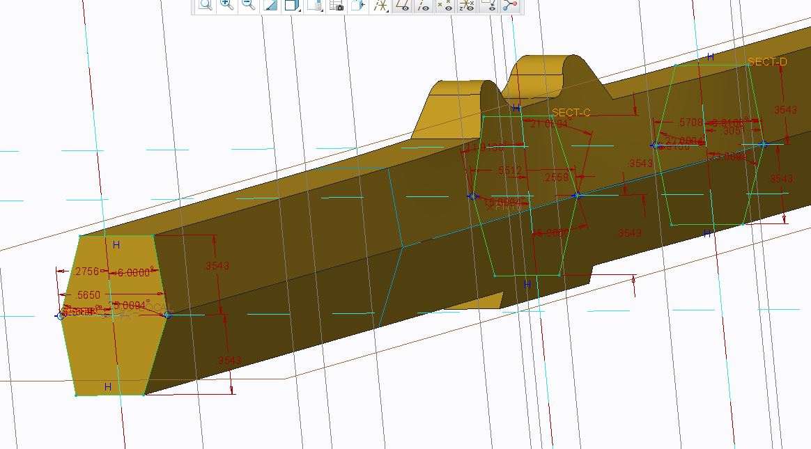
Sections.JPG


This thread is inactive and closed by the PTC Community Management Team. If you would like to provide a reply and re-open this thread, please notify the moderator and reference the thread. You may also use "Start a topic" button to ask a new question. Please be sure to include what version of the PTC product you are using so another community member knowledgeable about your version may be able to assist.

3 replies

pimm15-MoonstoneAuthor
15-Moonstone
February 24, 2015

I've made another simple series of sketches just in case it might help by setting up a simpler relation table. I can place this on the net if it would help.

SketchesWithDraftWalls.JPG

I'm thinking that I would like to tie all the sidewall features to a single draft feature from the 1st sketch. If I add a degree of draft to this single feature I'd like it to update the remaining sidewall drafts in the sketches by the same offset value.

1-Visitor
February 24, 2015

Hi Paul, maybe you are over complicating things here. Why so many sections? Maybe i am not fully understanding your finished geometry, so apologies if i am not. If i am understanding things right, i would have thought 2 sections, one at each end of the sweep would suffice, with a simple relation controlling the draft angle of sketch 2. If indeed you do need all 14 sections in your sweep, you certainly don't need 56 dimensions adding to the table, each sketch would only require 1 dimension. You need to create 'equal' constraints within the the sketch itself. Take your sketch 1, d26, d27, d28 & d29, i assume have the same value, in sketcher make then all equal, you only need change 1 dimension to manage the others.Then your relation might look something like d38=d26+1, d48=d26+2 & so on.

Hopefully this helps you out.

Regards

John

pimm15-MoonstoneAuthor
15-Moonstone
February 24, 2015

John,

I appreciate your reply to this confusing topic.

Unfortunately I think I over simplified the 2nd sketch set that I attached just to show a simple example. There might be an angle or 2 that happen to be the same draft but as a rule all the draft angles in the sketches are different values.

Based off your reply I should be able to control all the angles but it would require writing 55 different sets of equations based off of the original draft that 1 degree was added.

I will try this inside of my simple model with sketches.

I am wondering whether you could rename these 55 draft features to a common name that would add 1 degree of draft to each of these with only 1 equation line?

Patriot_1776
22-Sapphire II
February 24, 2015

Is it stepped, or a smooth blend? If stepped, that would explain 55 different draft features! If it's smooth, why not use a VSS (Variable Section Sweep)? You can use a graph feature to specify a changing angle.

pimm15-MoonstoneAuthor
15-Moonstone
February 24, 2015

Frank: Most of the models that I make I go with the VSS because it does a good job with matching up side walls.

With this job the customer left all of their section curves in the model so I could make my blocker stage of the model directly off of an exact replica of their model.

I have heard that it was possible to modify numerous dimensions based off of 1 driving dimension, with this I saw an opportunity for learning how this technique would be done.

In the future I would like to inquire how you can specify adding draft with a graph feature.

With this job I'd like to follow the pattern that was established by our customer. The model itself has replicated well. Adding draft however is posing a challenge.

Unless there is another quick way of adding a degree to each draft feature I am thinking I might punt and make this into a large family table model. With this I can bump up each column dimension by one.

John: I did try the formula you suggested but I would have to tweak the original value to replicate some very odd values +1 for a lot of features.

Patriot_1776
22-Sapphire II
February 24, 2015

Well, the thing with a VSS is that the other trajectories needto not have any steps normal to the origin trajectories. There can be an angle and they need not be tangent, but the step can't be normal. Or, if you want to vary it smoothly, put the angle dimension in the graph, and reference the graph in the VSS section relations.

Patriot_1776
22-Sapphire II
February 25, 2015

It'd be nice to see the geometry you're actually trying to create, as a image file, or, better, a STEP. Why the steps?

pimm15-MoonstoneAuthor
15-Moonstone
February 25, 2015

Frank:

I'll screen capture the other more complicated end.

Last sections.JPG

This is the reason for the sections. I copied these sections directly from the customer model. This view shows the sections fairly well but there also is a good degree of twist in which you can't see.

sections top.JPG

This picture shows the twisting involved with the datums.

I have used VSS successfully in the past in applications like this. The reason that I like this is that I was able to capture every draft angle value in a family table and by incrementing by 1 I could get a true value for this change. I would like to see how you might offset the corner intersection to reflect a 1 degree change with VSS, but this gives me a value I can trust. Unfortunately for customer proprietary reasons I can't release this model online.

John: Perhaps these pictures help explain what I'm trying to achieve. I was thinking that it would be best to show the simple part of this model, but it doesn't adequately describe the complications.

To be honest I am happy with the results I am getting from Family Tables. Someone today showed how I could use Excel to quickly change the angle value (of course that is once the numerous angle values already were captured)

I'm still holding out hope that there would be a way to parametrically change just 1 value to update all values, but until that time I'm fairly happy.

1-Visitor
February 25, 2015