1-Visitor
January 28, 2014
Solved

WF5: Using Curve pattern

  • January 28, 2014
  • 2 replies
  • 4156 views

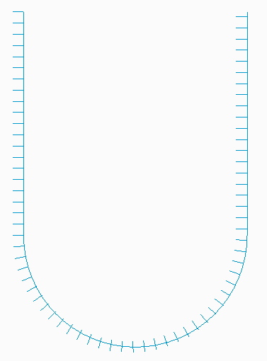
Try this - make a U-shaped datum curve. Then sketch a datum curve spine from the curve in the plane of the U-curve. Then pattern using the Curve option. The shape one should get is a U-shape with a bunch of lttle spines sticking out of the same side, like a beard, if the spine started towards the outside.

What I get in WF5 is spines that float away from the U in the radius portion of the curve and then reattach on the wrong side.

Apparently there is a flawed assumption made by the Curve pattern generator that the geometry is equally biased on the curve.

To 'fix' this I tried to add equal disposition about the curve. So I create the spine like I want, but had a tiny line segment on the other side that extends just as far away. Hopefully the little segment is not noticeable.

I then replaced the tiny segment with a geometry point (not the default sketch point, but the other one). This also worked as long as it was the same distance away from the curve as the furthest extent of the line.

I tried a construction circle, but apparently the flaw is in the geometry duplication stage.


This thread is inactive and closed by the PTC Community Management Team. If you would like to provide a reply and re-open this thread, please notify the moderator and reference the thread. You may also use "Start a topic" button to ask a new question. Please be sure to include what version of the PTC product you are using so another community member knowledgeable about your version may be able to assist.
Best answer by TomU

A picture is worth a thousand words. Same issue in Creo 2.0 M080.

crv_2.PNG

2 replies

TomU23-Emerald IVAnswer
23-Emerald IV
January 28, 2014

A picture is worth a thousand words. Same issue in Creo 2.0 M080.

crv_2.PNG

dschenken1-VisitorAuthor
1-Visitor
January 28, 2014

Tom, I marked it as correct so you get the points - I am presently bereft of a way to capture and post pictures.

I also found that if I want to project the curves onto a surface, I can't use sketched project and create a datum point. I have to create the pattern of a regular curve, then create a project using the geometry, and then pattern that Reference to the first curve pattern.

Perhaps there could be a YouTube unscripted channel for code reviews where we could see how it was decided that Curve pattern and projected sketches would work the way they do. Sort of like C-Span or sausage factories.

15-Moonstone
January 28, 2014

curve_pattern.jpg

use the alternate origin option, and select the start point manually.

i have done this in Pro|Engineer Wildfire 5.0 M010

Patriot_1776
22-Sapphire II
February 6, 2014

Ok, so, I was sort of wrong. You cannot select a 3D curve to pattern along. BUT, you can pattern along a 2D curve and use the option "Follow surface shape" and "As projected" to get this:

PATTERN_ALONG_CURVE-02.jpg

Note: On the "spike" curves, I have a 45deg angle, that's why the spikes are not normal to the curve.