1-Visitor
July 22, 2015
Solved

Which tool to use to create this shape (swept blend?, sweep?)

  • July 22, 2015
  • 4 replies
  • 4204 views

http://i.imgur.com/5X9Kgom.png

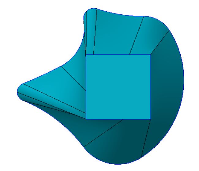
The picture above shows the outline of the shape I'm trying to make. I need to make a solid object starting from the squiggle shape, along the straight line which is the trajectory, and to finish into the square. I think the swept blend needs objects with the same number of sides to create this which it does not have, so how could I get around this? Thanks


This thread is inactive and closed by the PTC Community Management Team. If you would like to provide a reply and re-open this thread, please notify the moderator and reference the thread. You may also use "Start a topic" button to ask a new question. Please be sure to include what version of the PTC product you are using so another community member knowledgeable about your version may be able to assist.
Best answer by mpeterson

I used the boundary blend tool as I tend to gravitate to that because in the long run you can continue to modify your curves to control the transitions better. Hard to tell what the intent is one how this shape transitions from a square to a squiggly line. Attached is my model where I kept it simple to start and just use curves in one direction and then used control points to align points on each curve with the associated points on the other curve. If need be you could create curves in the second direction connecting specific locations between curves and also possibly making the curves in the second direction not straight with their own curvatures. The image is a view of the attached CAD file.

boundary blend trial.JPG

4 replies

mpeterson1-VisitorAnswer
1-Visitor
July 22, 2015

I used the boundary blend tool as I tend to gravitate to that because in the long run you can continue to modify your curves to control the transitions better. Hard to tell what the intent is one how this shape transitions from a square to a squiggly line. Attached is my model where I kept it simple to start and just use curves in one direction and then used control points to align points on each curve with the associated points on the other curve. If need be you could create curves in the second direction connecting specific locations between curves and also possibly making the curves in the second direction not straight with their own curvatures. The image is a view of the attached CAD file.

boundary blend trial.JPG

1-Visitor
July 22, 2015

Swept blend requires the same number of control points, not the same number of sides.  It the example that Mark posted, he added points around the square to make it match the number of control points on the "squiggly line" enclosed shape.

Patriot_1776
22-Sapphire II
July 29, 2015

...or you could use a VSS.....

Patriot_1776
22-Sapphire II
July 30, 2015

...Like this surface (easily "closed" to be a solid)....

VSS_BLEND-01.jpg

1-Visitor
July 30, 2015

Frank,

In Creo, the VSS command is gone; PTC reworked the sweep and blend commands.

Regardless of all that, what did you use to generate that render?

Patriot_1776
22-Sapphire II
July 30, 2015

Well, I'm on creo elements/pro 5.0, whatever the h3ll that means now.  I know it's a couple revs behind.  Hopefully they have taken the VSS capabilities and just moved them.  It's one of their most powerful tools.  If it's gone, I'm gonna be totally p!$$ed.

Just added a color and turned on the "Enhanced Realism) with the shade quality set to 10, nothing special.  I'd rather put my effort into the model, not the rendering.