14-Alexandrite
November 13, 2015
Solved

WYSIWYG PDF Output for Subset of Creo Parametric Line Content?

  • November 13, 2015
  • 5 replies
  • 3385 views

We are using Creo Parametric 2.0 M170 and Windchill PDMLink 10.2 M020. Our pen table on the CAD Worker for publishing PDFs is as follows:


pen 1 thickness .030 in; color 0.0 0.0 0.0

pen 2 thickness .015 in; color 0.0 0.0 0.0

pen 3 thickness .020 in; color 0.0 0.0 0.0

pen 4 thickness .015 in; color 0.0 0.0 0.0

pen 5 thickness .015 in; color 0.0 0.0 0.0

pen 6 thickness .015 in; color 0.0 0.0 0.0

pen 7 thickness .015 in; color 0.0 0.0 0.0

pen 8 thickness .015 in; color 0.0 0.0 0.0


We have a symbol for designating bar code location that appears like this on the Creo Parametric drawing:


Bar Code Symbol on Creo Parametric Drawing.jpg

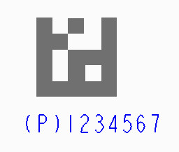
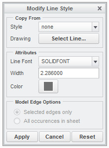
The text is going to Pen 2 (system color for Letters), the lines of the graphic are going to Pen 1 (system color for Geometry). Here are the line style settings:


Bar Code Symbol Line Style Settings.jpg


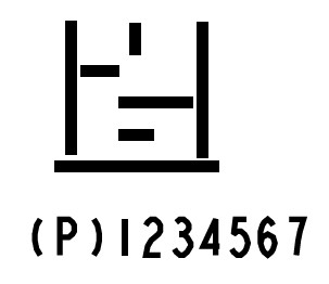
When the PDF is published, it looks like this:


Bar Code Symbol on PDF from CAD Worker.jpg

Based on discussion with PTC, Knowledge Base and Community searches we have tried using the following Config.pro settings on the CAD Worker, neither had any impact:


  • pdf_use_pentable no (even though it seemed counter-intuitive )
  • use_software_linefonts yes


After going through the PTC guidance on pen tables we are very hesitant to consider assigning the line color to one of the lesser used pens (5-8) and making that pen thicker; we assume that this would have unintended consequences for other drawing content items eventually.


To summarize, we are thoroughly stumped. Does anyone have advice on other alternatives to try? Much appreciated, in advance!


This thread is inactive and closed by the PTC Community Management Team. If you would like to provide a reply and re-open this thread, please notify the moderator and reference the thread. You may also use "Start a topic" button to ask a new question. Please be sure to include what version of the PTC product you are using so another community member knowledgeable about your version may be able to assist.
Best answer by dschenken

Accurate artwork has always been a chore to get out of Pro/E and Creo, obviously extended to Windchill publisher. Notice that the numeral "1" is shorter than the "2" That's because pen plotters make a circular mark and the difference in height is the diameter of the expected pen; the font 'font' is designed for pen plotting. When PTC started using Postscript they used the wrong options for setlinecap and setlinejoin, using 0 and 2 instead of 1 and 1 like they should have, making the text output Flintstones crude. They also used to prioritize assigned widths over pen table entries, but reversed their position a number of years ago, making any width management an extreme chore.

What should work, but probably won't, is to outline the areas and then fill, followed by putting just the outline on a layer and blanking it.

Another workaround is to create a 3D model with raised areas, then create an area section and fill that. Erase the edges.

5 replies

dschenken1-VisitorAnswer
1-Visitor
November 14, 2015

Accurate artwork has always been a chore to get out of Pro/E and Creo, obviously extended to Windchill publisher. Notice that the numeral "1" is shorter than the "2" That's because pen plotters make a circular mark and the difference in height is the diameter of the expected pen; the font 'font' is designed for pen plotting. When PTC started using Postscript they used the wrong options for setlinecap and setlinejoin, using 0 and 2 instead of 1 and 1 like they should have, making the text output Flintstones crude. They also used to prioritize assigned widths over pen table entries, but reversed their position a number of years ago, making any width management an extreme chore.

What should work, but probably won't, is to outline the areas and then fill, followed by putting just the outline on a layer and blanking it.

Another workaround is to create a 3D model with raised areas, then create an area section and fill that. Erase the edges.

1-Visitor
November 14, 2015

For the logo to be precise on a PDF it's better to model it as a surface and put a shaded view of the model onto the drawing.

Changing the pentable is not a good way to go.

24-Ruby III
November 16, 2015

David,

your pentable contains:

pen 1 thickness .030 in; color 0.0 0.0 0.0

pen 1 definition contains thickness .030 in, therefore all geometry lines will be plotted 0.03 in thick. thickness property overrides 2.286 thickness of bar code lines.

If you remove thickness .030 in from pen 1 definition, then you will get correct bar code.

So use the following pen 1 definition and test its functionality.

pen 1 color 0.0 0.0 0.0

MH

1-Visitor
November 17, 2015

You are right, Martin.

Just tested that, and now i stand corrected!

Too bad Creo doesn't let the user select the *.pnt file during the export to PDF. Either way, nice find.

DavidCobb14-AlexandriteAuthor
14-Alexandrite
November 17, 2015

Hi all,

Thanks for the suggestions! We were working on redoing the symbol as suggested by David, and have now tried Martin's suggestion also and it works just as he said.

Whilst I'd love to start celebrating, I'm a bit confused now. On the test drawing all of the "Geometry" entities assigned to Pen 1 are still showing the same thickness that they did on the PDF before we removed the thickness .030 in parameter. That's what we want, but I don't really understand what's happening. Questions swirling in my head:

  1. How can we remove the thickness parameter, but seemingly not have any impact on the other entities that were using it?
  2. Are there some sort of default pen thickness values that are coming into play when no thickness parameter is explicitly specified?
  3. Is removing the thickness parameter going to have any unintended consequences that we're not thinking of/seeing at the moment?

Thanks tremendously in advance for any additional education you can provide to a confused novice!

1-Visitor
November 18, 2015

1&2) Geometry has built-in defaults for thickness.

2) Thickness is a parameter for each piece of text and drawing curve. It's possible the drawing template has those values already set.

3) Plotting in Creo is all about unintended results. You can tell from the lack of a precedence order chart in the documentation.

DavidCobb14-AlexandriteAuthor
14-Alexandrite
January 4, 2016

Hi all,

Many thanks for the great feedback and suggestions!

Both the suggestion by David to outline and fill, then remove the outline and Martin's suggestion to remove the thickness parameter from Pen 1 produced the desired results. We decided to implement the change to just the symbol for the moment; however we've seen a couple of other line thickness issues we're still considering the pen table change as an option for. We are a lot more cautious about doing that since it's hard to test everything else that might be impacted.

We are very grateful for the contributions from your experience and knowledge, it has definitely been a huge help! I foresee having more questions in the future that will benefit from your expert assistance.