

Question
Changing sketch reference
I am trying to run a sensitivity analysis between the length of a crank shaft and it's max_stress_vm. However when the simulation runs and the length is increased an extruded hole does not move along with it. I am just wondering if it is possible to make a sketch reference a difference point so that when the length is increased it maintains the same distance between its centre and the edge. 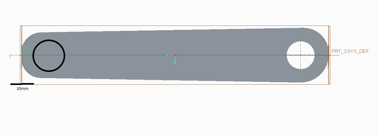
I want to ensure that the black circle is 10mm from the green co-ordinate system rather than being 100mm from the original co-ordinate system.
Thanks for any help.
This thread is inactive and closed by the PTC Community Management Team. If you would like to provide a reply and re-open this thread, please notify the moderator and reference the thread. You may also use "Start a topic" button to ask a new question. Please be sure to include what version of the PTC product you are using so another community member knowledgeable about your version may be able to assist.