1-Visitor
March 20, 2014
Question

Creating Degrees of Freedom in Weighted Link

  • March 20, 2014
  • 1 reply
  • 7242 views

Capture.PNG

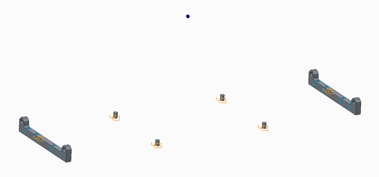
In this simulation I have a large box that is simplified to a point at its center of gravity (blue point in image above). The box is tied down to the floor using the 4 vertical locating pins and 4 horizontal pins going through the 2 pin block parts. I am trying to model the stresses in the pins and pin blocks, thus I need to transfer the inertial load of the point mass to these surfaces but only in the directions that make sense for the pin connections. How might I do this?


This thread is inactive and closed by the PTC Community Management Team. If you would like to provide a reply and re-open this thread, please notify the moderator and reference the thread. You may also use "Start a topic" button to ask a new question. Please be sure to include what version of the PTC product you are using so another community member knowledgeable about your version may be able to assist.

1 reply

13-Aquamarine
March 21, 2014

Hi Justin,

I would try using an Advanced Spring at each pin connection. Create two points with a small separation, probably easiest if they're aligned along the pin axis. Connect one point to the pin surface with a weighted link, connect the two points with the spring and connect the 'other' points to the box CG with (I think) a Rigid Link.

If I remember correctly the default is for the Y-axis of the spring to be defined along the direction between points, so if you give the spring a fairly high stiffness in X and Z displacement, and zero in Y displacement and all three rotations, that should be a good starting point. (If you think the pins will react tilt loads then you might want to also try making the tilt stiffnesses fairly large.) Given that it's essentially the same connection at each point, you should be able to define a single Spring Property and use it for each connection.

For stiffness values, choose something that's just high enough to keep the displacements insignificant. If your reacted load was 1000 N then you might say that you can accept 0.01 mm displacement without worrying, so you'd use 1000÷0.01 = 1e5 N/mm. Going too stiff can hurt convergence.

jpratt-21-VisitorAuthor
1-Visitor
March 24, 2014

Jonathan,

Thanks this seems like an approach that could work. However, in attempting this solution I discovered that I can connect two weighted links to a single point and define degrees of freedom in those weighted links. I figured I would give this a shot first.

I made a point along the axis of each pin and created weighted links from the pin surfaces to the points. While defining these weighted links I chose to constrain the degree of freedom along the axis of the pins. I then connected those points to the mass with one weighted link with all degrees of freedom enabled. The model ran and completed. Do you see any reason for this to misrepresent what I intended? Capture1.PNG

2-Explorer
March 24, 2014

Can you post more information on how you set up your weighted-links? As I understand your model, I would have expected you to get a collinear error due to how you defined your weighted-links.