Simulation results seem unrealistic compared to real test
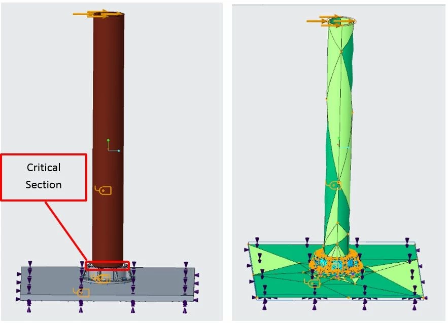
Using a mechanical testing machine I have determined that the bending strength of a hollow circular shaft with brittle material to be about 18 KN at the height of 1.47m. The force was applied perpendicular to the shaft axis at the top end. The attached image shows the simulation setup similar to the real test.
ID and OD of the cross section of the shaft are 0.13m and 0.18 respectively. The breaking stress due to bending has been calculated (momentum/section modulus) as 63 MPa at the critical section where it gets constraint . I have been using this value to compare the results from simulations.
Simulating this bending test in Creo, I find quite different results:
1- Using solid body mesh, the stress is about (Max Principal) 150 MPa at the critical section
2- Simulation Live in Creo Parametric shows Max Principal to be 82 MPa
2- Using mid-surface shell, the max principal is about 108 MPa at the critical section
3- When using shell it is possible to exclude membrane and shear, so the stress due to bending becomes 54 MPa
Here are my questions:
1- Why should we see such high gaps among results from real test, simulkation live, and simulations using shells and or solids?
2- Why the membrane stress is so high (about 57 MPa) in this setting when using shells? (please note the shear stress was quite small and could be neglected and also the mass of the component is 95 Kg)
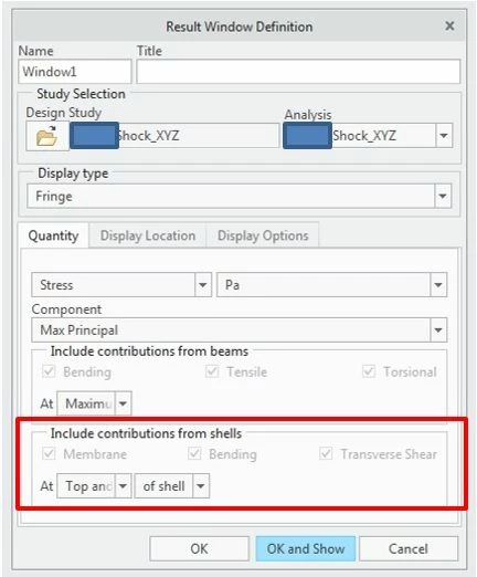
3- We use the component in a structure that should be tested against shock after finding mode shapes. Surprisingly, when using shell elements it is not possible to exclude membrane after performing the shock study. Is this a software limitation?
A screenshot of the results configuration window for a shock study is attached.