
13-Aquamarine
May 26, 2026
Solved

Creating a spiral toolpath with trajectory milling that ends in a true diameter

  • May 26, 2026
  • 1 reply
  • 7 views

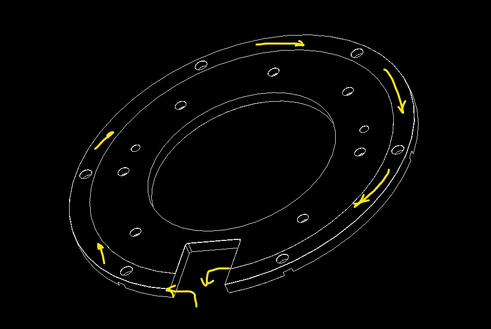
I’ve been trying to make a spiral tool path that starts on the OD of a part and winds inward until it reaches a step in the part where I would like the toolpath to make a finish circle around the step.

I’ve come very close by using edge of a curve by equation and a sketched diameter, but for whatever reason, Creo seems to want to retract before it is done.  Ideally it would stop and start within the tooth area.

This is a 40” diameter part with the step on the outside being .017” +/-.001, so I am trying to get the best finish I can on this surface.  I am thinking this will be around 20 windings as it works its way to the center diameter.

I don’t really like the result of cutline or volume milling.  I’m not sure why trajectory isn’t working exactly as I see it should either.  Maybe if the whole path could be created by a curve by equation it would?


Best answer by KenFarley

Two ways I could approach this:

(1) Use the Mill->Classic NC Steps->Custom Trajectory and define all the curves explicitly for the tool to follow. You need to set the hidden config option ENABLE_CLASSIC_NC_STEPS to YES to use this type of toolpath.

(2) Make a mill surface of the region you are trying to machine. When you define the surface you want to fill the six holes. Use a Mill->Milling->Surface Milling toolpath. Select the mill surface, set your STEP_OVER to whatever increment you want to use for your multiple swirls. In the Define Cut portion of the definition, you want to define two cut lines, the first at the outer diameter, the second at the inner (on your mill surface). Once everything is defined as such, you need to go back into the parameters and set the SCAN_TYPE to TYPE_HELICAL. This will make the path spiral round and round, pitched with the specified STEP_OVER and should do just what you want. To use the Surface Milling type of cut, you need to have another hidden config option ENABLE_CLASSIC_CUTLINE set to YES.

Both of these are reliant on toolpath construction methods that PTC seems to feel are not necessary. No one asked me, though.

1 reply

KenFarley
KenFarley21-Topaz IIAnswer
21-Topaz II
May 26, 2026

Two ways I could approach this:

(1) Use the Mill->Classic NC Steps->Custom Trajectory and define all the curves explicitly for the tool to follow. You need to set the hidden config option ENABLE_CLASSIC_NC_STEPS to YES to use this type of toolpath.

(2) Make a mill surface of the region you are trying to machine. When you define the surface you want to fill the six holes. Use a Mill->Milling->Surface Milling toolpath. Select the mill surface, set your STEP_OVER to whatever increment you want to use for your multiple swirls. In the Define Cut portion of the definition, you want to define two cut lines, the first at the outer diameter, the second at the inner (on your mill surface). Once everything is defined as such, you need to go back into the parameters and set the SCAN_TYPE to TYPE_HELICAL. This will make the path spiral round and round, pitched with the specified STEP_OVER and should do just what you want. To use the Surface Milling type of cut, you need to have another hidden config option ENABLE_CLASSIC_CUTLINE set to YES.

Both of these are reliant on toolpath construction methods that PTC seems to feel are not necessary. No one asked me, though.

razmosis13-AquamarineAuthor
13-Aquamarine
May 26, 2026

I went with option #2.  I had the classic nc steps, but not the classic cutline.  It’s been quite a while since I’ve seen that classic cutline menu.  The result is exactly what I was looking for!

Thank you!

Matt
