1-Visitor
October 18, 2013
Question

How to represent a milling along a 3D path

  • October 18, 2013
  • 2 replies
  • 3310 views

Hello,

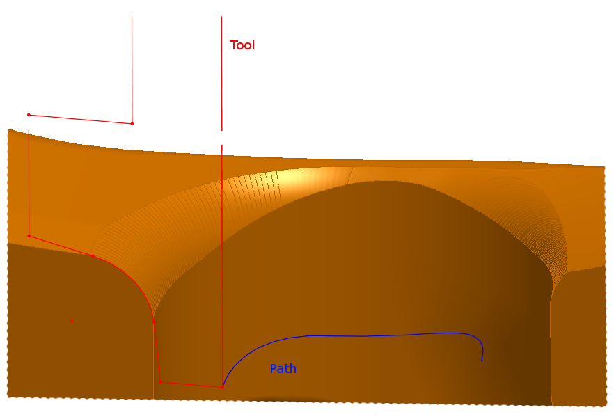
I would like to represent a milling with a special tool and along a 3D path. The only way I found is to create a repetition of substraction of the tool along the path but is not very clean.

Do you have an idea how to do that ?

Sans+titre.png

Thanks in advance,

Regards

PS : I work on WF4


This thread is inactive and closed by the PTC Community Management Team. If you would like to provide a reply and re-open this thread, please notify the moderator and reference the thread. You may also use "Start a topic" button to ask a new question. Please be sure to include what version of the PTC product you are using so another community member knowledgeable about your version may be able to assist.

2 replies

12-Amethyst
October 18, 2013

There is no straight forward tool for this : regular Sweep tools only address flat sections, while in true material removal cutting curve is anything but flat.

In some particular cases you can simulate true tool path though, especially if we talk 3 axis milling. This require quite extensive surfacing work, but the guidelines might be :

1. Define mill axis path by 2 curves (one passing through the tip of the mill, another - passing through some point on its axis)

2. Make boundary blend between these curves

3. use normal offset of this blen to both sides, with offset = R of the tool. With sime luck, these normal offsets wil emulate very close the true material removal boundaries.

4. close this path from the bottom side (either by another blend, or by full round - if this is ball mill).

5. Merge all surfaces and solidify them. If it all succeeds you may get a "negative" side, that you will need to just subtract from your material.

This worked for me once building spiral flute for a drill, hope this will work for your case too ...

Best

- Vlad

1-Visitor
October 18, 2013

Thank you for your answer, I'll try it.

Regards

12-Amethyst
October 18, 2013

One more item I forgot to mention : given construction of this "negative" part is quite a task by itself, it is much easier to make it as a separate "material removal" part, and then locate vs. material and perform cutout. If you try to work in the same part you will face more problems in quilts work / solidification than working in an empty part.

Patriot_1776
22-Sapphire II
October 18, 2013

This is one area where SolidQuirks is actually better. You can sweep a revolved solid along a trajectory, more accurately simulating the path of a rotating cutting tool.

We've needed this for a long time, I've run into issues because of this.

Actually, in looking at your geometry, a simple swept cut should work. Your trajectory looks planar.

1-Visitor
October 18, 2013

Thank you but my trajectory is not planar...

What is "SolidQuirks" ?

Patriot_1776
22-Sapphire II
October 18, 2013

Ahh, it looked like it was. In that case, you could do a pattern of sections (put points at a relative position on the curve, pattern the points, then reference pattern the curves), and do a blend thru the sections. While this won't be perfect, it'll be real close, especially if there's a bunch of sections.

Oh, and "SolidQuirks" is a jab at "SolidWorks" CAD software.

Good luck!