

Trajectory Milling
Had some free time to work on this today. Source link
I created a curve by equation and used that to drive a trajectory milling sequence for some long slots I needed to mill.
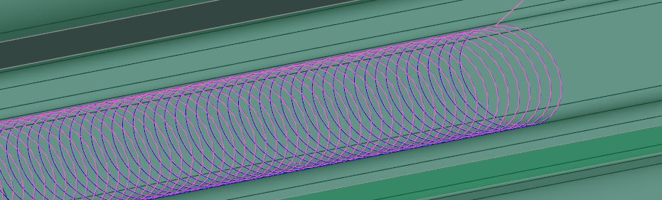
here is the equation I used to create this curve.
/* ENTER TOOL STEP OVER
SO = 0.05
/* EMPIRICAL VALUE TO CORRECT SHAPE ERROR
SF = 0.0175
/* ENTER PROFILE ALLOWANCE (STOCK)
PA = 0.005
/* ENTER TOOL CUTTER DIAMETER
CD = .3937
/* ENTER SLOT WIDTH
SW = 0.811977
/* ENTER NUMBER OF REVOLUTIONS
N = 100
A = ( ( SO * SF ) / 3.141592654 ) / 2
B = ( ( SW - ( 2 * PA ) ) - CD ) / 2
x = ( A * ( t * N * 360 )) - ( B * sin ( t * N * 360 ) )
y = ( B * cos ( t * N * 360 ))
z = 0
I don't understand what the shape error value is about but it seems to work for this application. Just thought i should share this with everyone in case they wanted to use it or improve it 
This thread is inactive and closed by the PTC Community Management Team. If you would like to provide a reply and re-open this thread, please notify the moderator and reference the thread. You may also use "Start a topic" button to ask a new question. Please be sure to include what version of the PTC product you are using so another community member knowledgeable about your version may be able to assist.