
Question
Circuit analysis
I'm not exactly sure what is causing the error of if I'm doing something completely wrong
Circuit is shown 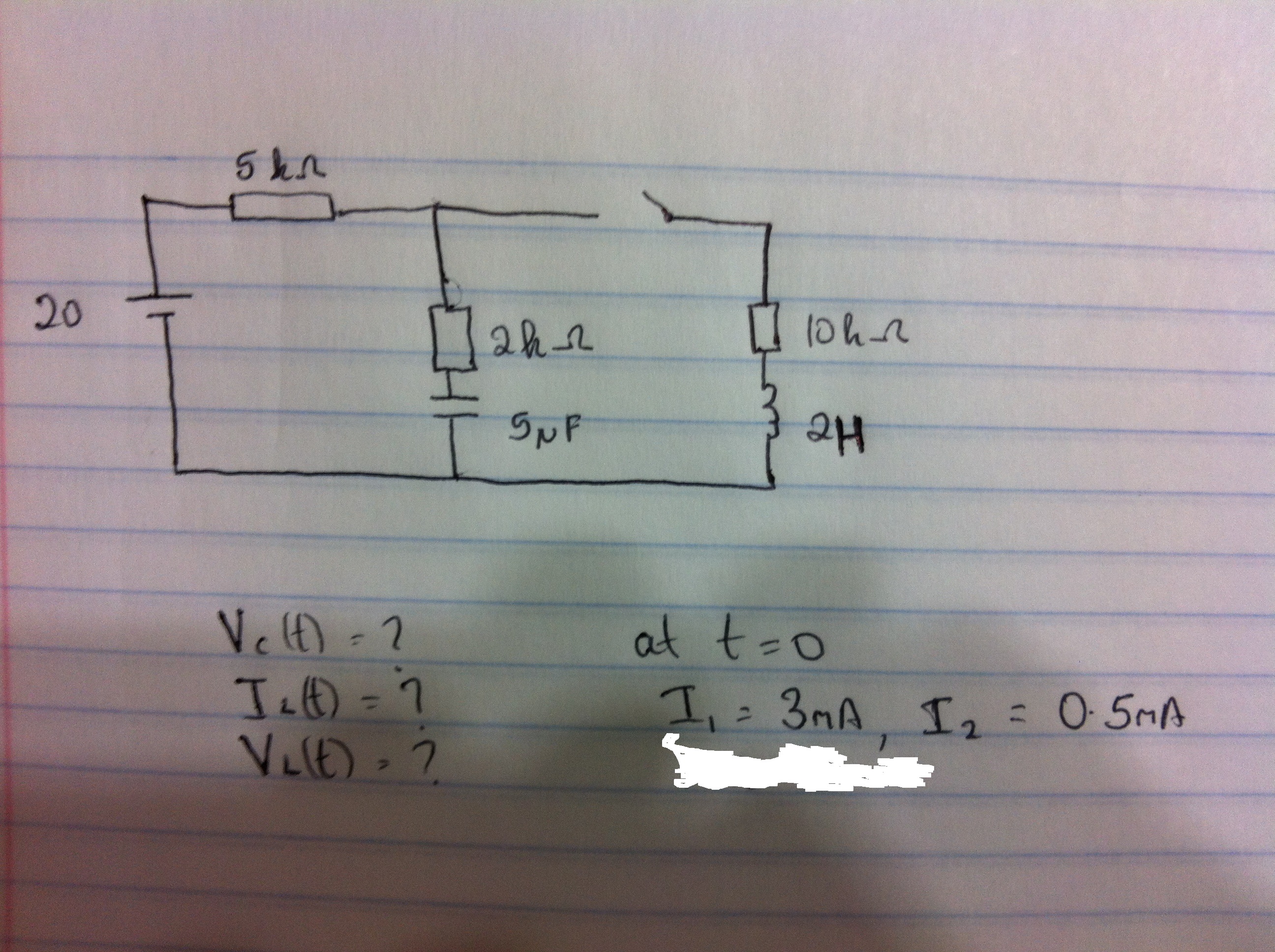

No account yet? Create an account
Enter your E-mail address. We'll send you an e-mail with instructions to reset your password.