1-Visitor
November 20, 2015
Solved

Help With An Instrumentation Amplifier

  • November 20, 2015
  • 5 replies
  • 7490 views

I'm trying to make an instrumentation amplifier with a 10v/v gain. My friend asked me for help, and I'm a little embarrassed to say that I couldn't help her out, but her question piqued my curiosity.

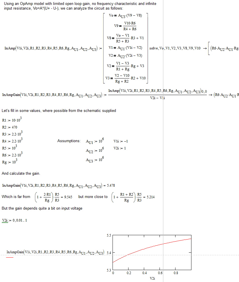
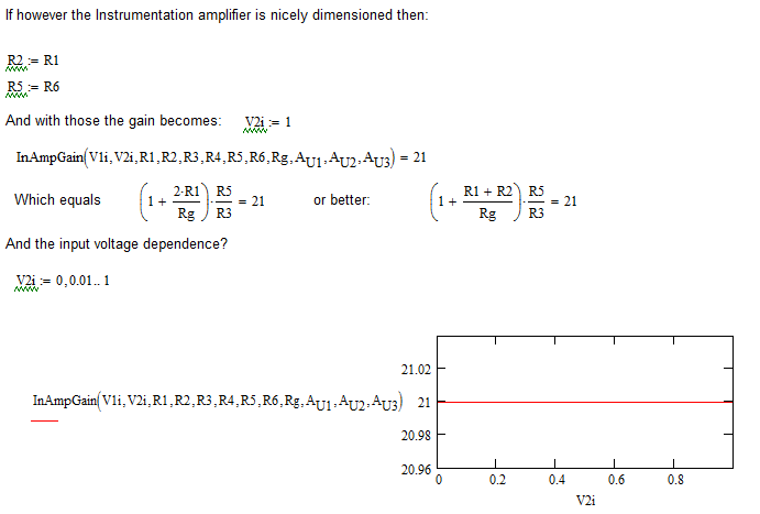
From what I knew, gain was decided by the following equation:

(Vout)/(V2-V1)=(1+(2*R1/Rgain))(R3/R2)

But every time she tested it, she got some strange result. Am I wrong about 10v/v meaning that Vout=10(V2-V1)? How can I make this work? Any help would be appreciated.

Here's a link to what we're working with.

Best answer by LucMeekes

If you analyse it more thoroughly:

This should explain why the Instrumentation amplifier wasn't reacting as expected.

This gives a fixed gain, independent on input voltage.

Luc

5 replies

23-Emerald IV
November 20, 2015

You have a very non-symmetrical instrumentation amplifier: why is R2 value different from R1's?

You are putting a lot of input on the V2 input. What is your power supply range, and does it accomodate 19 V input?

Have a look at the internals of an industry instrumentation amplifier, e.g. INA 121: http://www.ti.com/lit/ds/symlink/ina121.pdf.

Success!
Luc

21-Topaz II
November 23, 2015

Hello LucMeekes!

What do you think about my solution?

Bye

23-Emerald IV
November 24, 2015

I think your analysis is OK, but doesn't match the schematic Here's the original poster (OP) is working on.

The two feedback resistors in there (R1 and R2) are completely different in value. whereas you have them (Rf and Rf) nicely exactly the same.

Plus the OP is putting an awefull lot of voltage into one input, and I cannot see the supply voltage. In your analysis you're starting off from idealized OpAmps, (infinite supply, infinite open loop gain) which is OK if these factors don't play a significant role.  The simulation on the other hand must take account the supply voltage and (I hope) uses realistic models of the OpAmps used. I don't think it's strange that the simulation gives results that are unexpected ("But every time she tested it, she got some strange result.") if you use the setup as depicted with the gain formula { (1+2*R1/Rg)*R5/R3 } that applies to a nicely balanced instrumentation amplifier. The picture shows that that would result in a gain of 11.6... In fact if I fill in his data, I get a gain of:

But the InAmp doesn't have 2x10k for R1 and R2. It has 10k and 470, and with those values I might try:

This should explain part of the "strange result". The other part may have to do with the large input on V2, which would probably clamp one input of OpAmp U2.

Regards,

Luc

21-Topaz II
November 20, 2015
23-Emerald I
November 20, 2015

Attached is a schematic and calculation for a two stage  amplifier with a gain of 400 and a 100 Hz low-pass filter.

Built, tested, works.  Adjust as needed.

Derbigdog
15-Moonstone
November 24, 2015

Maybe this can help.

scurtis1-VisitorAuthor
1-Visitor
November 24, 2015

I wish I could list you all as correct answers, thank you so much for your help!