1-Visitor
June 13, 2017
Solved

Mechanism, spring graphics connected to wrong body.

  • June 13, 2017
  • 2 replies
  • 5776 views

Hello.


I have recently started to use Creo Mechanism which is a bit finnicky and not user friendly but I think I am slowly getting the hang of it.

I have set up a mechanism with a spring between two bodies. This seems to work as intended however the graphical representation of the spring has decided to follow the motion of a different body altogether. Does anyone know what is wrong here?


I attach a picture that tries to illustrate the problem.


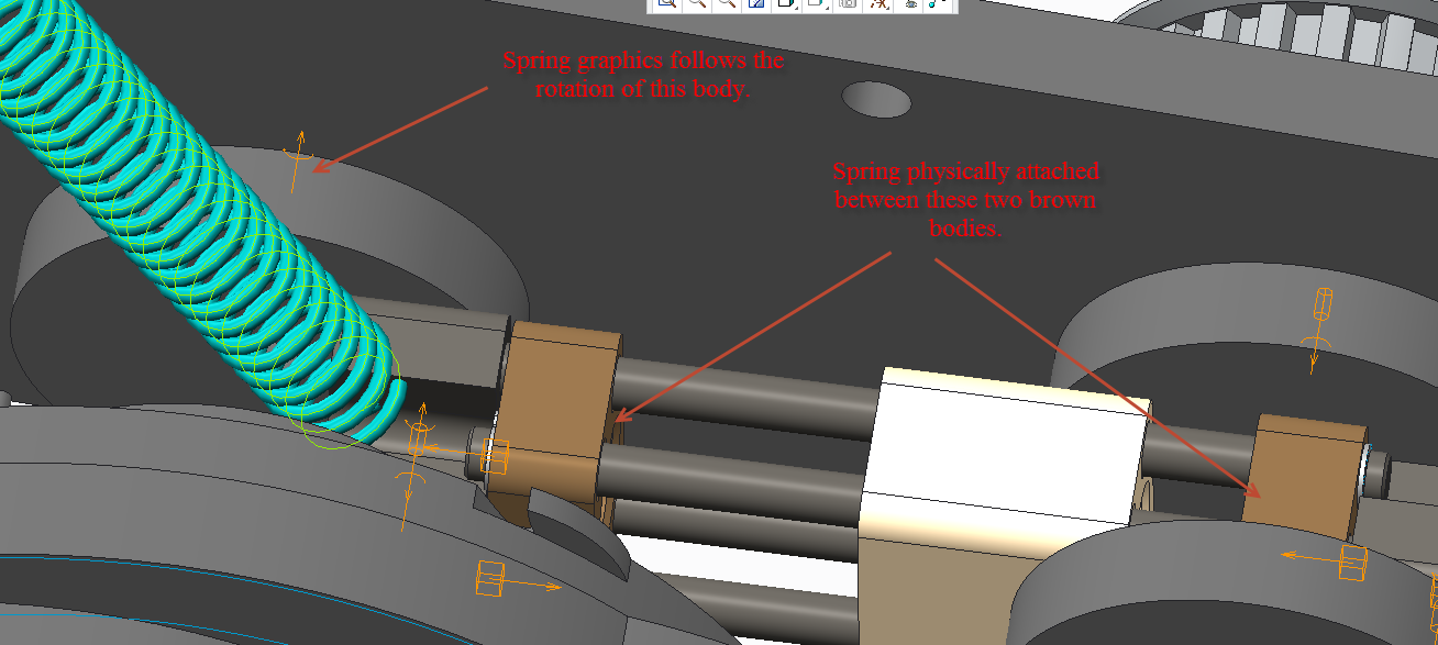
It is a small problem but it is not fun to explain to anyone that the simulation is probably physically correct and that it is just the graphics that are wrong.


Kind regards

Jimmie

Best answer by jhansson

I have solved it now but I still think it is a bug but with a workaround.

The two points I used to connect the spring was not located in respective part but in the assembly that these parts belonged to. However the points was located in the correct body within mechanism so I thougth that should be fine and as I mentioned physically the spring behaved correctly. But when I changed the points to be within each part instead also the graphics followed the simulation correctly.

Thanks for all the help!

2 replies

16-Pearl
June 13, 2017

I have never seen this issue after using springs many hundreds of times. How is your spring connected? Are you using a joint spring or point-point? This should not occur unless you've somehow tied the spring to the rotating body. If the spring is properly assigned/defined, this is a bug.

jhansson1-VisitorAuthor
1-Visitor
June 14, 2017

I am using a point to point spring and the respective points are located in the bodies representing the brown blocks, one in each. The beahvior of the analysis are also consistent with a spring being located between these two bodies. I would probably also guess that it is a bug.

16-Pearl
June 14, 2017

OK, there's one more thing to look at before PTC may want to call it a "bug" - you'll need to go through the entire assembly to make sure that all your components are very formally connected to just one body...what I mean by this is, within each joint all the constraints should always only be defined between the two same bodies. It is easy to select a reference that appears to be from the body you intend, but Creo may pick-up another similar datum from an adjacent body and you may not realize it. Often MDX/MDO will work fine this way, but at times certain functions will not behave properly if just one reference is from the wrong body. It normally shows-up as goofy result graphics, like the one you're seeing.

Hope this helps,

Chris

14-Alexandrite
June 19, 2017

It is not user-friendly as you said, and it is not easy to solve also. I would use a point to point spring and check ALL my connections again. Remember, your first component of an assembly MUST BE CONNECTED AS DEFAULT. Otherwise, ¨funny¨ things can appear in mechanisms.

1-Visitor
June 20, 2017

I'd like to add to this discussion and mention that often the "default" constraint won't work for me if I leave the connection as "user-defined".  Then, if I change the placement definition for this component to be of "Rigid" type and and voila! - it works.  I'm still learning so I can't explain better, but I'd say that in general, if you are dealing with mechanisms, then use mechanism connections and avoid using the standard "user-defined" mates / constraints.  And definitely avoid the use of that "allow assumptions" checkbox.