1-Visitor
July 11, 2014
Solved

Any one got a good 3D printer?

  • July 11, 2014
  • 2 replies
  • 6361 views

Hi Tim/Every one!

As you know we've got a basic printer as school and it works OK but- now that we've got going with Creo I'm experimenting with intefacing components to make "real world" products.
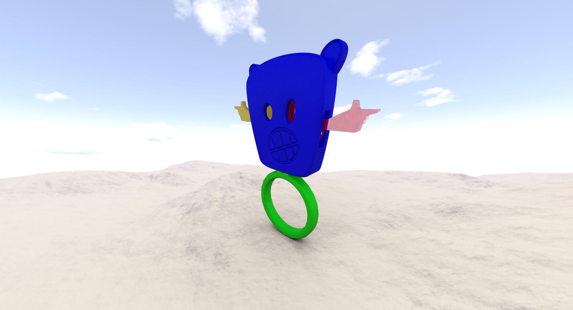
BUILD2.jpg

Its a ring and when you wiggle your fingers the arms move!
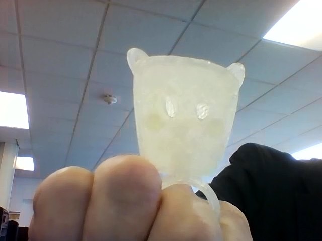
Snapshot_20140711.JPG

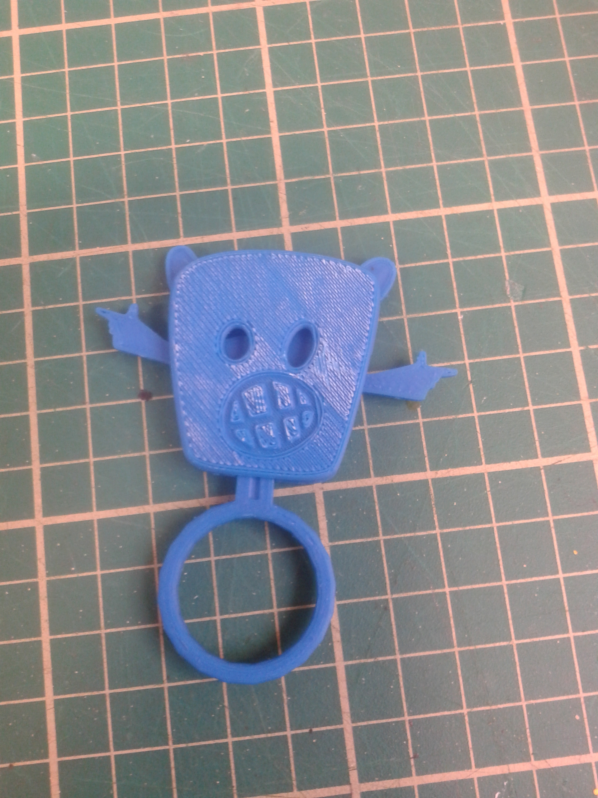
Except our 3D printer is struggling to print the arms.

I've uploaded the Creo file (any suggestions on getting the meech right?) and an stl version if anyone owoud like to have a go at tthe product.

Let me know how you get on and hoow the parts interfaced.

Best regards

Peter
    Best answer by JeremyConnaught

    Hi Peter

    printed your design on an Up Plus 2

    20141001_150307.jpg20141001_150315.jpg

    no problems and worked fine. printed it face down to get the insides clean for the mechanism, otherwise loads of support removal and cleaning up would be required. as it is a quick rub with wetand dry would make it shine.

    Jeremy

    2 replies

    12-Amethyst
    July 11, 2014

    Peter,

    I love the idea of kinematic jewellery! It's great to see designs being manufactured.

    You don't specify the problem with the arms. Are they too thin, could you beef them up a bit?

    If you are getting separation between layers, it helps if you get the bed/chamber up to operating termperature before you start the build. Avoid cold rooms and anywhere there might be cold air/drafts.

    The STL export from PTC Creo gives control over the mesh size. The attached instructions explain how to get a fine mesh.

    .

    It might be possible to get your models made on a professional 3D printer, I'll email someone I know and copy you in.

    I'm looking at how you assembled the parts in Creo and think there miight be a better way. I'll check it out and, if it works, I'll upload the result here.

    Keep up the great work!

    Tim

    PeterSach1-VisitorAuthor
    1-Visitor
    July 11, 2014

    Cheers Tim,

    Thanks for the pdfs.

    I'm having problems controlinng the "squash" effect and the inteference sizes. The arm thickness is alright & we've got no kids in today so theres no cold air being swirled around!

    Have a good weekend

    Peter

    12-Amethyst
    July 11, 2014

    Peter,

    Attached is the assembly with different constraints.

    • On the link(ring) I replaced your planar connections with a slider connection and limited the vertical movement to 3.75 mm.
    • I replaced the pin connections on the arms with cylinder to allow them to float along the axis. This was need for the slot connections below to work.
    • I created a datum point at the base of the circular bosses in the arms.
    • Sketches were created in the link(ring) along the centreline of the slots.
    • Slot connections were created between the datum points in the arms and the sketched lines in the link.

    The model should move kinematically using the drag tool.

    Let me know what you think.

    Cheers

    Tim

    PeterSach1-VisitorAuthor
    1-Visitor
    July 11, 2014

    Thanks Tim,

    I'll have a good look at the file.

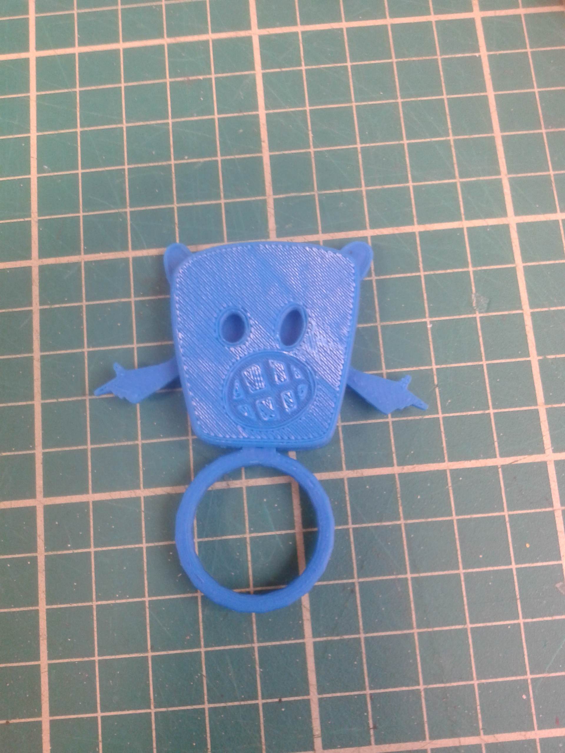
    Got a good print out this afternoon.

    Pics below.

    2.png

    3.png

    And an attched avi of the physical assembly.

    Have a good weekend

    Peter

    12-Amethyst
    July 11, 2014

    Brilliant, well done!

    Which 3D printer are you doing this on?