

Belt Features in Mechanism Design
New in Pro/ENGINEER Wildfire 5.0 Mechanism design are belt features. This allows for the connectivity between any rotating axis, simulating belts and pulleys. Not only can the kinematics of the belt pulley system be simulated but dynamics and forces can also be analyzed.
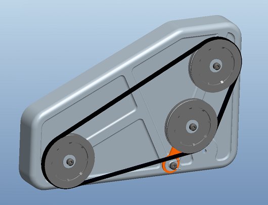
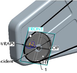
Defininging and setting up the belt and pulley system is a simple process. First, using the control key select the pulleys you want to connect. In the Dashboard you can optionally define the stiffness of the belt, in this case 5000N. This is not required for creating the belt, but is very important for analyzing the forces in the mechanism and the belt itself. It is easy to add or remove pulleys at any time. Using the right mouse button (RMB) you can easily adjust the belt trajectory or switch the pulley order. Selecting the  button allows you to set the belt length, otherwise the length is determined by the pulley geometry.
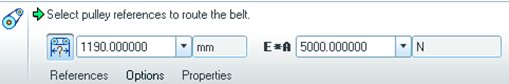
The number of wraps can also be defined by double clicking on the “WRAPS” icon in the graphics window.
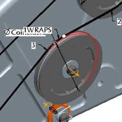
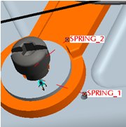
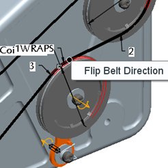 If there is a tensioner in the belt loop, it will automatically adjust to any change in the length of the belt. A right mouse button pick on the round dragger icon allows you to flip the belt direction.
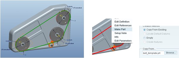
Finally, center the belt on the pulley using a central datum plane on one of the pulleys, Right mouse button on the datum plane and select Belt Plane.
Optionally you can set the diameter of the pulley independently of the pulley geometry. Simply select a joint axis and enter the desired diameter or change the diameter inherited from the selected pulley.
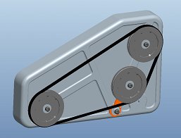
The belt definition is now complete. Pushing and holding the Ctrl and Alt keys and then dragging any pulley shows the system motion.
Once the belt is routed, a solid part representation of the belt can be constructed that is associative to the belt feature. Select the Belt Feature from the model tree, right mouse button, “Make Part.” A dialog opens allowing you to name the new part and specify a template part to use. Next you will be asked to assemble the new part, use the default constraint, middle mouse button to complete the part.
The belt curve can now be used to extrude a solid profile, or you can use it to construct a chain with individual links.
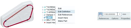
 From the model tree select the belt feature (make sure you have selected the check box to display features in the model tree settings, tree filters.) Change the belt length, regenerate and see how the belt updates.
Torsion springs have been enhanced in Pro/ENGINEER Wildfire 5.0, letting users select spring arm references that represent how a “real” torsion spring would attach. Strict control of joint axis settings is no longer necessary to define a torsion spring thus saving time. Simply reference a rotational axis, the attachment points of the spring arms and enter a spring constant K.
 Now let’s check to see if the tensioner is doing its job. By placing a servo motor on one pulley and a load torque on another, we can analyze the tensioner angle vs. time as the motor starts. This is a dynamic analysis working against the load in the belt, the belt flexibility, and the torsion spring. Belts also have specific measures available like tension and slip.
Create an analysis using a servo motor on one pulley and a torque load on another, use the parameters show. Then run the analysis.
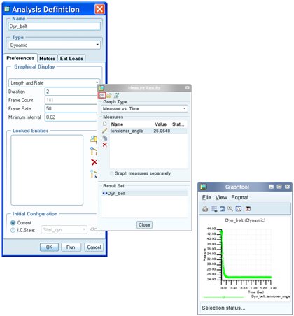
Once the analysis is done graph the results.
This thread is inactive and closed by the PTC Community Management Team. If you would like to provide a reply and re-open this thread, please notify the moderator and reference the thread. You may also use "Start a topic" button to ask a new question. Please be sure to include what version of the PTC product you are using so another community member knowledgeable about your version may be able to assist.