1-Visitor
December 1, 2016
Solved

Is there a way to display sketcher lines outside of sketcher mode?

  • December 1, 2016
  • 6 replies
  • 17919 views

Hi All,

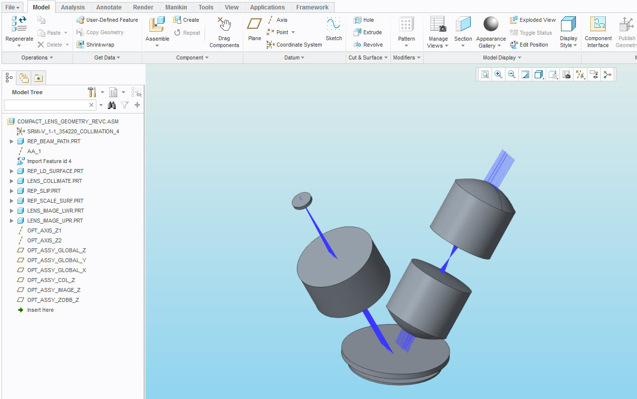
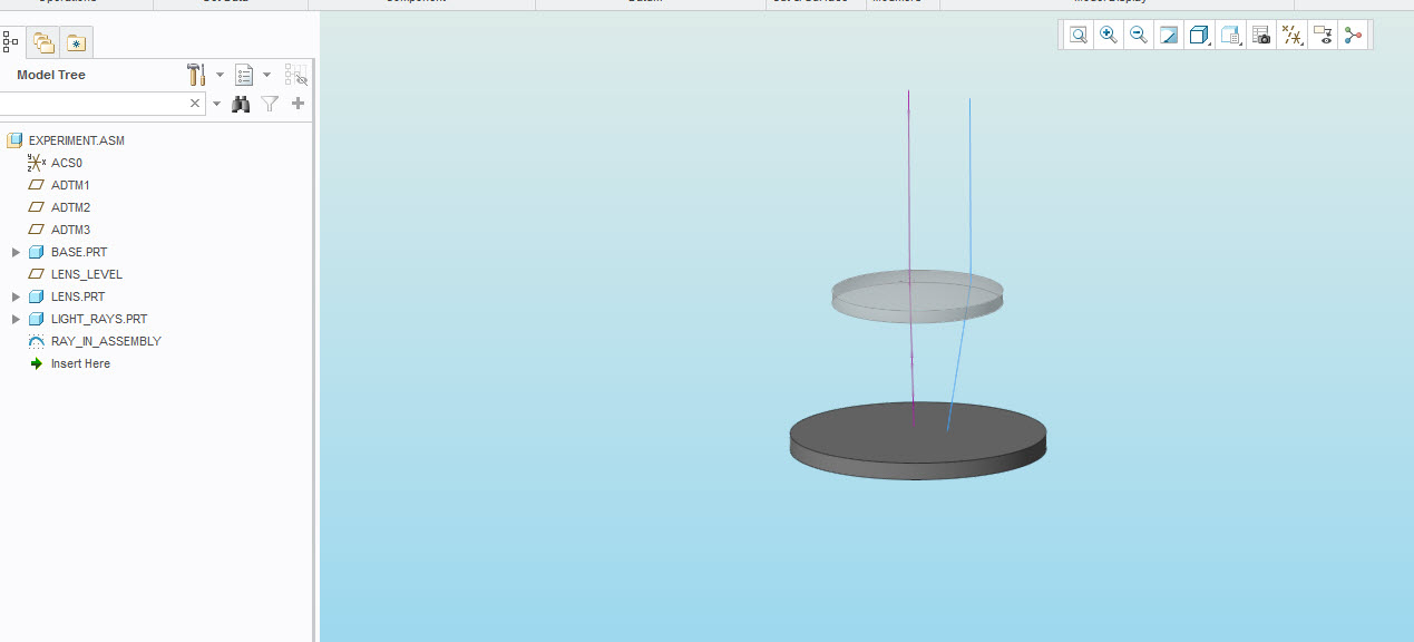
I'm using Creo 3 and am unable to find a solution. I am wondering if it is possible to display sketcher lines while outside of sketcher mode when creating a part. Let's say you have a simple cube made from an extrude and you then select a face of that cube to draw on--a line for this example's sake. Once I click okay and exit sketcher mode, the line is not visible unless I hover my cursor directly over it. In my line of work this can sometimes be a major annoyance and I'd like to see sketches outside of sketcher if possible. Is there a way to change this?


Thanks


This thread is inactive and closed by the PTC Community Management Team. If you would like to provide a reply and re-open this thread, please notify the moderator and reference the thread. You may also use "Start a topic" button to ask a new question. Please be sure to include what version of the PTC product you are using so another community member knowledgeable about your version may be able to assist.
Best answer by mperkins

I just found the solution to my problem. While looking into the various configuration settings and files that Creo uses, I found my Creo admin's config.sup file that we use. There was a setting in there called "shade_with." The description for this setting is:

shade_with

curves*, no

Displays datum curves on shaded objects.

I changed it from "no" to "curves" and it immediately resolved the issue. I believe that I didn't resolve the issue previously because I was making changes to config.pro and if I'm not mistaken config.sup has has priority and will override any conflicting settings to the config.pro file. I also do not think any settings from config.sup are displayed in the Creo configuration editor, so it wouldn't have come up when I was trying to find keywords. In any case, it is doing what I expect now.

2016-12-05_7-08-54a.jpg

2016-12-05_7-09-49b.jpg

Thanks for the help everyone.

6 replies

1-Visitor
December 1, 2016

Sketcher is the basis for creating features. I expect you made some feature and that feature is on a blanked layer and is placed there because of layer rules or layer default configuration options.

Add a screen capture taken just before you click the green OK checkmark in the sketcher so that we can see the options that are selected for the sketch.

mperkins1-VisitorAuthor
1-Visitor
December 1, 2016

I've already looked at layers and came up empty handed. The layer display changed, but only when I was in sketcher mode. It didn't make the sketch viewable after exiting sketcher. What options and config settings change sketch display outside of sketcher? I think that will get me there faster than a screenshot that won't show much.

Also, I understand that sketcher is usually used for features, but in this case (not always) I am working with optical light rays. They are zero thickness in essence, but I want to treat them as lines so I can then dynamically change angles, lengths, etc. of the light rays and constrain other features to them. I can do this as is, but I have to hover over the datum line to even see it. It is difficult to select the correct ray when there are 100+ of them and you can only see them when you hover over. I found that a temporary workaround is to view the model in a wireframe mode, but this isn't a 100% perfect solution for me.

23-Emerald III
December 1, 2016

You're using a stand alone sketch feature? Or?

12-Amethyst
December 1, 2016

If the sketch isn't being used to make a feature, consider making a datum curve feature that references the sketch.

mperkins1-VisitorAuthor
1-Visitor
December 2, 2016

Fair enough. I still feel like this is a workaround and not a solution. I already have several workarounds and can get the job done, so this is really just about what is "right" and what Creo should do. Unless I'm misinterpreting the actual workings, I've seen what I'm trying to do done successfully. This guy does it:

How to Model Involute Spiral Bevel Gear in PTC Creo - Gleason System Part 1 - YouTube

1-Visitor
December 1, 2016

Let me make sure I am guessing what is happening to you correctly.

You make a sketch on a face of an already made cube.

The sketch consists of a line.

When you click on the green arrow to accept and finalize the sketch, the line "disappears".

Subsequently, when you hover over the area of the cube where you "painted" this line, then the line is highlighted.  This rules out the possibility that the sketch has been placed on a blanked layer automatically.  By default your sketches will be automatically hidden if you use them as the basis for other features (extrudes or revolves).  But that's not what you are doing, so basically, I think that either: a) you have a graphics card issue or b) your colors are such that the sketched lines are hard to see in the graphics area...  Try switching to a "wireframe" display mode, to see if the line is indeed there (--> problem b).   Also try setting the config.pro setting graphics win32_gdi (problem -->a).

mperkins1-VisitorAuthor
1-Visitor
December 2, 2016

The first part of your post is correct in terms of the symptoms I'm experiencing and example given.

I looked at layers and this doesn't appear to be a factor.

I don't always use these sketches for subsequent geometry, and in fact they disappear before I get to that point either way. I don't think it is a graphics card issue because my coworkers experience the same thing. I also have a decently beefy graphics card and think the win32_gdi setting is oriented more for low end cards, correct? A quick Google search said to only switch from OpenGL to that if you were experiencing issues due to hardware limitations. I have my card running at full AA with high quality edges and most of the other graphics enhancements and it doesn't bat an eye, so I am skeptical in thinking that my card can't handle what I'm asking.

1-Visitor
December 2, 2016

The win32_gdi setting is for when the graphics system is malfunctioning and that can happen to very high end cards that happen to have the wrong or incompatible drivers loaded to operate them. It is primarily a diagnostic tool to see if there is a flaw in the OpenGL subsystem.

In fact, the more fun options you have turned on the more likely it won't work right.

Is it an AMD card?

17-Peridot
December 2, 2016

The key term in your post is "annoyance", Maxwell.

First of all, I find the default templates annoying only because they have intelligent layers.

I start nearly every part using save-as for similar things, or start with "empty" parts and assemblies.

These can easily be turned into "your flavor" template.  I haven't found a use for doing so.

You also have two kind of sketches... sketches and sections.  Sections are "private" where sketches are "public".

Private means the sketch was created while creating the feature.  Public means the sketch exists as a stand-alone entity.

In sketches, you can use geometry and construction geometry.  This is what determines if it remains visible.

Datum sketch features also have these two distinctions.

If you need reference data, keep the reference sketch and the feature sketch(section) as independent feature as a guideline.

If your system is acting normal, this should solve your problem:

  • start with an empty part
  • create your sketch
  • utilize your sketch geometry within next-level sketches and sections.

Also know that you have 3D datum curves, curves from equations, curves from cross-section, graphs, geometry edges, etc. for reference data.

17-Peridot
December 2, 2016

You might also try removing all appearance changes from the render tab.

It is an option in one of the appearance manager windows.

If your system behaves differently from what I outlined above as a simple test, you could create a support case.

mperkins1-VisitorAuthorAnswer
1-Visitor
December 5, 2016

I just found the solution to my problem. While looking into the various configuration settings and files that Creo uses, I found my Creo admin's config.sup file that we use. There was a setting in there called "shade_with." The description for this setting is:

shade_with

curves*, no

Displays datum curves on shaded objects.

I changed it from "no" to "curves" and it immediately resolved the issue. I believe that I didn't resolve the issue previously because I was making changes to config.pro and if I'm not mistaken config.sup has has priority and will override any conflicting settings to the config.pro file. I also do not think any settings from config.sup are displayed in the Creo configuration editor, so it wouldn't have come up when I was trying to find keywords. In any case, it is doing what I expect now.

2016-12-05_7-08-54a.jpg

2016-12-05_7-09-49b.jpg

Thanks for the help everyone.

5-Regular Member
December 5, 2016

Thank you for sharing your final solution Maxwell.

Best,

Toby

1-Visitor
December 5, 2016

Well, you learn something everyday.  This one has some prank potential.

17-Peridot
December 5, 2016

Interesting find, Paul.

I do not know where the config.sup file comes in but I always keep an "original" desktop link to know I am booting "Ceo out of the box".

This helps eliminate any config issues.

Thanks for posting!

1-Visitor
December 5, 2016

The .sup file is supposed to allow company admins to ensure a consistent product by placing them in the not-overrideable config.sup and placing it in the Creo startup path. How it often ends up is the admin gets a complaint from one user and, rather than investigating it, they find an option that ruins the Creo experience for everyone to hide the original problem.

My favorite is an admin thinking to force some standard mapkeys into .sup. Since .sup locks in -only one- value for the config option, not only does it define exactly one mapkey, it makes certain that no one else can create them. (Unless PTC has changed this in Creo specifically; that was the way it worked for a very long time.)