

stl modelling, a tale of three software pacakges
H i All
I have a problem which we need a workable solution for.
We need to make this as simple as possible as we are looking at processing this on evey batch of wheels so we can alter the programming to best suit the wheel, as heavy wheels damage our machinery.
We are trying to intergrate three software application to work as one process
these are
Creo 1.0
Vericut Machining simulation
Tecnogamma lazer scanner
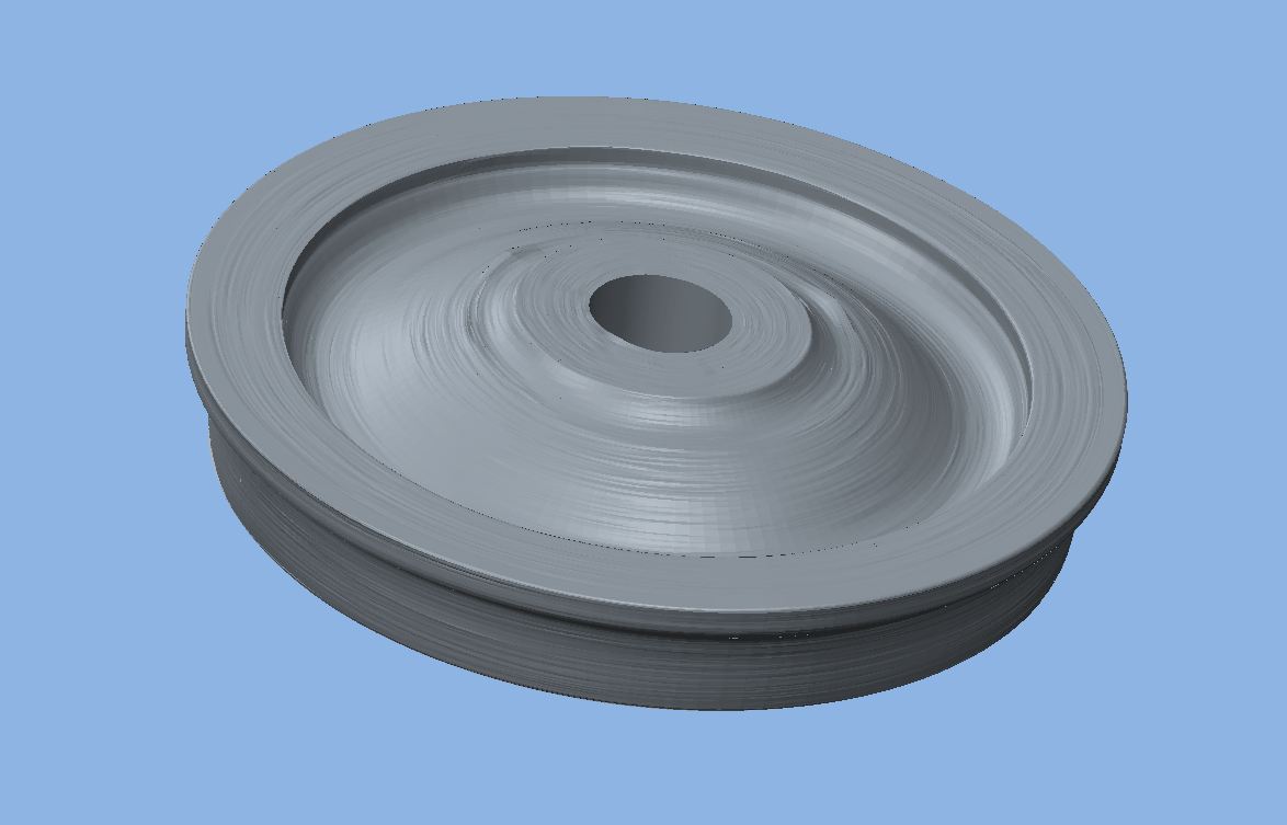
What we are doing, the lazer scanner measures the hot forged wheel at the end of the roll process and it create a 3D STL file of the wheels surface from the collected data. as below
Now we are trying to load this into Vericut, so we can get an idea of just how much metal is really being removed, but it doesn't like the fact that it is not concentric.
So, I have been trying to create a cross section by loading the STL file into a part and then creating a cross section, with the idea that I can use a sketch to create a revole feature for both the heavy side and the light side of the wheel to estimate the runout, I can then run the simulation on both and calculate the mass removed on each cut for both models.
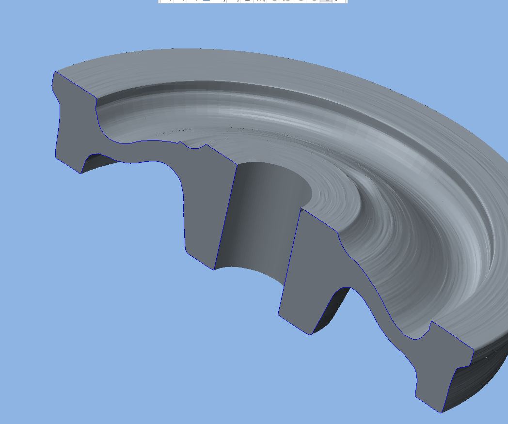
Now the problem is, I can get this far, but it won't reference the STL part to allow me to create a sketch. I would just like to sketch on half of the cross section to create a revole feature.
Is there a solution to this
Thank you
Peter
This thread is inactive and closed by the PTC Community Management Team. If you would like to provide a reply and re-open this thread, please notify the moderator and reference the thread. You may also use "Start a topic" button to ask a new question. Please be sure to include what version of the PTC product you are using so another community member knowledgeable about your version may be able to assist.