12-Amethyst
August 6, 2018
Solved

assembling a bolt&nut pre-assembled assembly

  • August 6, 2018
  • 10 replies
  • 8170 views

Hi there,


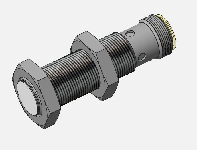
Just wondering, I have an assembly with a sensor and two nuts attached and I would like to place this sensor assembly onto a number of brackets with different wall-thicknesses (meaning the position of the nuts will be different for each wall thickness). What is the most efficient solution here? Create a new sub-assembly of the sensor-and-nuts for each bracket or is there a smarter solution, eg. something with flexible parts (Im using Creo 3 with AFX)? How could I do that?
 

Clipboard01.jpg

Best answer by StephenW

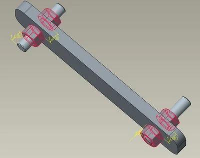
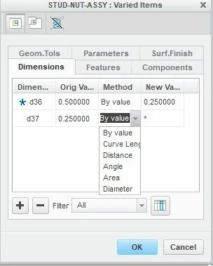
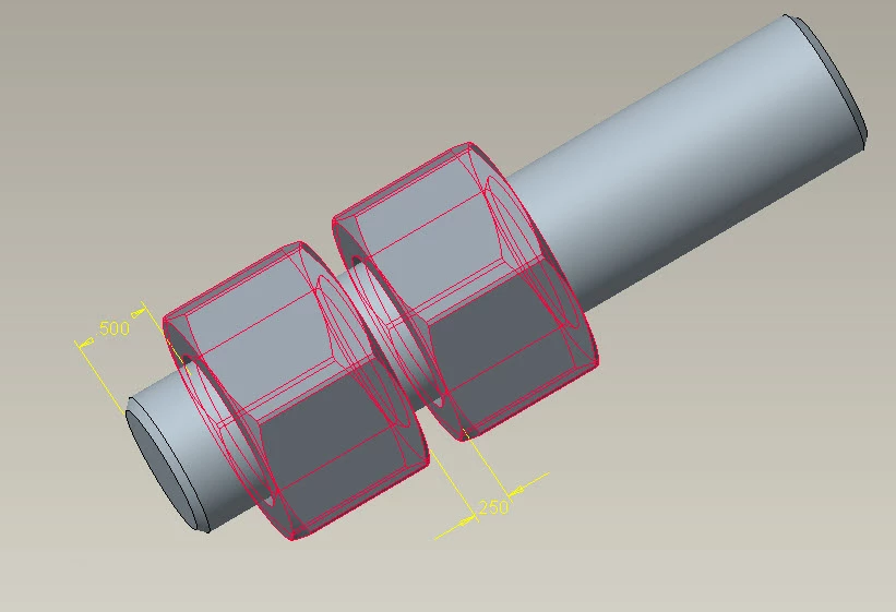
I set up a stud-nut assy with these 2 dimensions pre-defined with flexibility.

stud-nut.jpg


Then when I assembled, I used the pre-defined flexibility to enter the values of the offset of the first nut from the end of the stud and the offset of the second nut from the first nut. (thickness of the mounting panel)

test-assy.jpg


You can also use the tools in the flexibility dialog box to determine the panel dimension if you don't know it.

flex.jpg

10 replies

SamuelBrantner
16-Pearl
August 6, 2018

Hi @BJP,

in Creo 4.0 with AFX 4.0 we made it possible to assemble connector / equipment elements with flexibility.

I could forge an example if you can update.


Greetings Sam

Greetings Sam
BJP12-AmethystAuthor
12-Amethyst
August 6, 2018

that would be AWESOME!

kdirth
21-Topaz I
August 7, 2018

I would suggest using predefined flexibility.  Assemble sensor with first nut relative to end and the second relative to the first.  Then follow the following:

  • To predefine flexibility in a component or assembly go to File / Prepare / Model Properties. Select “change” for Flexible under Tools section.
      • When part or assembly is assembled into an assembly you will be prompted to use predefined flexibility.
    • Select a feature or part to flex, select dimension to vary, and select OK.
    • Repeat for additional feature or part flexibilities.
    • Select OK.
  • To add flexibility when adding part with predefined flexibility.
    • Select Yes to prompt “Would you like ot use it for flexible component definition?”
    • Add new value for flexibility dimensions as needed and select OK.
There is always more to learn.
BJP12-AmethystAuthor
12-Amethyst
August 8, 2018

I've tried this and it should work but.. for some reason I cant select dimensions in my model although the nuts are assembled with an offset. Does this sound familiar?


Actually I would like to assemble the sensor with two options: 

1. fill in a distance of the front nut with respect to the front of the sensor and mate the sensor on a bracket

2. mate the front face of the rear nut on a bracket in the main assembly. (perhaps with mechanism constraint?)

See attached image. Should this be possible at all?


Clipboard02.jpg

kdirth
21-Topaz I
August 8, 2018

Be sure you are applying flexibility to the sensor assembly in your assembly and be sure to select the nut not a feature of the nut.


I have not been able to get the additional mate for the second nut to work.  I thought that leaving that constraint off the assembly or assembling it with mechanism would allow it to be constrained in the final assembly similar to how I have assembled moving cylinders.

There is always more to learn.
16-Pearl
October 16, 2018

I'm wondering, do you actually want this to be a subassembly? It seems to me like you get an unnecessary level in your Bill of Materials. I think an Assembly User Defined Feature (UDF) might be more appropriate in some situations.


Assembly UDFs are at the 2:34 mark of this video:

https://www.youtube.com/watch?v=Zb5ey4OthW0&t=