

1-Visitor
May 22, 2014
Solved

Easiest way to use a centreline when...

  • May 22, 2014
  • 22 replies
  • 14112 views

I'm having terribly difficulty understanding how I can create a centerline on a surface so that sketches and extrudes cutouts can be made "in the middle".

Maybe my starting point was wrong? This is what I've done:

  • I've created a sold part by sketching the "base" to be 110mm wide by 300mm deep. My CSYS is the front left point.
  • I've then extruded that sketch to be 45mm tall, so now my CSYS is at the bottom front left of the case.
  • I now want to sketch some cutouts on the front of the case, and these are to be centered (so the mid point of these cutouts is 55mm offset from the origin of my CSYS on the X axis).

Now of course I can create a vertical centreline that's 55mm offset, but the issue is that if ever I change the original width of the case (first sketch that was then extruded), I have to change my centreline.

Is there not a way to create a centreline on a surface so if the dimensions of that surface change over time, so too will the position of the centreline?

Would I be better off moving my whole model so that the CSYS is in the middle of the front face on the X-axis? Or create a secondary set of coordinates and use that as the reference point for the sketches on the front surface?


This thread is inactive and closed by the PTC Community Management Team. If you would like to provide a reply and re-open this thread, please notify the moderator and reference the thread. You may also use "Start a topic" button to ask a new question. Please be sure to include what version of the PTC product you are using so another community member knowledgeable about your version may be able to assist.
Best answer by BrianMartin

Hi Xavier...

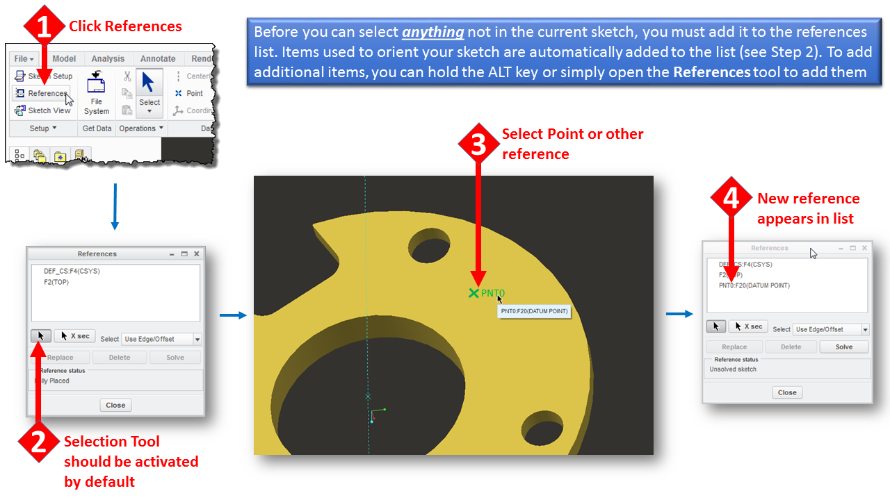
It's also selectable without the ALT key. You just have to add it to the references list before you can select it. This goes for any reference not in the current sketch. Hitting the ALT key is just a shortcut to add a new reference to your list of available references.

Select the slide below to view a larger version (easier to read).

add+to+references.png

I just didn't want you to get hung up on the ALT key. It's just a shortcut to save time. There are other ways to add references.

Thanks...

-Brian

22 replies

17-Peridot
May 22, 2014

In your primary sketch, you can create a geometry centerline rather than a construction centerline (the centerline on the left of the ribbon). I call these datum axes centerlines because they create a datum axis for selection once the sketch is complete. Same goes for points and CSYS'.

You can constrain this centerline in the sketch in one of many ways so it always stays centered. In subsequent sketches, you can now reference this axis created in the subsequent sketch.

Hope this all makes sense. Give it a try and see if this doesn't work for you. Of course, I am assuming you are on Creo 2.

17-Peridot
May 22, 2014

If you only want the centerline in one sketch, you can do this with assigning an equal constraint to two dimensions...

equal_constraints_on_2_dims.PNG

14-Alexandrite
May 22, 2014

As they say, if you ask 10 different people, you'll get 10 different answers for something like this, AND on top of that, I would do it different ways depending on what features I think I will modify later. So this is just another idea. But I will say drawing the X inside the rectangle seems time consuming.

centholes.JPG

1-Visitor
May 22, 2014

The quickest way is to create a datum point on the edge and set it to .50 ratio. Then reference that in your sketches.

An alternative is to add a measurement from one face to another and create a parameter using that measurement; locate the centerline with a dimension set equal to half the measurement.

Another alternative is to create the original part symmetric about the default datums.

xwalker1-VisitorAuthor
1-Visitor
May 22, 2014

Thanks David. I already tried making data points, but when I try that, they are created outside of the sketch and then not accessible within the sketch, even when I place them before.

As soon as I enter sketching on the surface, I can no longer reference / select the edges of the surface.

I'll have another look when I get back in front of the PC.

Thanks again

1-Visitor
May 22, 2014

They are selectable as sketch references.

Or you can select the align function and Pick from List to get the point.

70% guess - formerly used Solidworks? Only guessing as the number one complaint from SW users is not having open season easy selection of existing geometry in PTC's Sketcher Intent Manager.

xwalker1-VisitorAuthor
1-Visitor
May 24, 2014

Thanks Brian for those invaluable pieces of information. Would those slides be part of a wider guide that's publicly available? It looks like it's right up my street for the level and kind of information that I'm finding really useful.

Quick community forum question: can one no longer mark answers as helpful once a single answer has been marked as correct? I've "un-corrected" my earlier post (detailing the use of the alt key) and put your first reply as the "correct" one, but cannot add your second post as helpful (even after I had the marked the topic as unanswered). I would have thought that the ability to mark posts as helpful, would be, well, helpful especially as there can be several posts that all contribute to the "correct" answer... And I guess that can then help others find the answers to previously asked questions quicker!

17-Peridot
May 24, 2014

Relations are a very power tool and are used at many levels. However, I try to use them as a last resort at the sketch level. It is too easy to build in a relation that requires two regenerations to complete at all levels. -If- I can resolve a sketch with design intent using geometry, I will do this before considering relations at this level.

Having said that, building relations at feature level or part level is more reliable. there are times when a part is considered fully regenerated where the provided information is actually out of date. If the system considers the regeneration complete, it will not attempt to complete those things not up to date.

The easiest way to create such a failure is to use section relations (such as values or calculations) in model annotation.

xwalker1-VisitorAuthor
1-Visitor
March 24, 2015

Sorry to drag this back up, but I'm having a similar issue now using Creo 3.0.

I essentially want to add a new cooridnate systems to a 6.3mm Faston part (taken from here‌).

One ref on the flat plate (mating connector), a second centered on the disc surface on the cable side.

Maybe the part I've imported prevents me from doing this? But no matter what I try, I cannot get it working. It looks like the menus are slightly different too, maybe I'm not using the correct "Reference" menu?