

1-Visitor
July 28, 2015
Solved

Help! sanity check needed

  • July 28, 2015
  • 11 replies
  • 3701 views

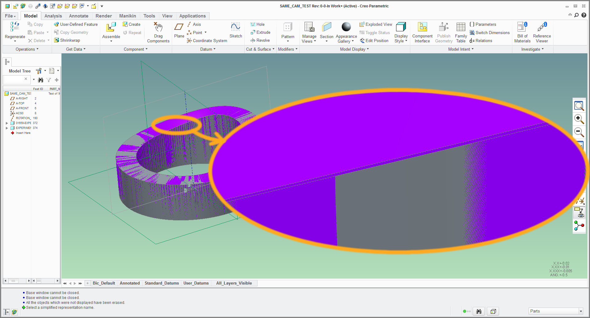
Hello everyone; can someone please save my mind because I don't understand why the final geometries of these 2 parts are different.  Attached is the assembly of experiment5.prt (gray) and 01659_experiment6.prt (purple).  They have the same feature tree, because the latter is a copy of the former.
slight_difference.png


FYI, I edited the definition of some sweeps in the copy as I was trying to learn the modeling technique.  I don't think I made any changes, but clearly something is different.

I'm using Creo 2.0 M160.


This thread is inactive and closed by the PTC Community Management Team. If you would like to provide a reply and re-open this thread, please notify the moderator and reference the thread. You may also use "Start a topic" button to ask a new question. Please be sure to include what version of the PTC product you are using so another community member knowledgeable about your version may be able to assist.
Best answer by Inoram

cammer.JPG

11 replies

Chris3
21-Topaz I
July 28, 2015

I haven't opened your files, but have you done a compare part by geometry to verify that they are actually different and its not just a graphics issue?

Capture.PNG

12-Amethyst
July 28, 2015

for the graphic side, you may also try changing your shade quality from default 3 to 10

file > options > model display > set shade quality to: <10>

Inoram14-AlexandriteAnswer
14-Alexandrite
July 29, 2015

cammer.JPG

psobejko1-VisitorAuthor
1-Visitor
July 29, 2015

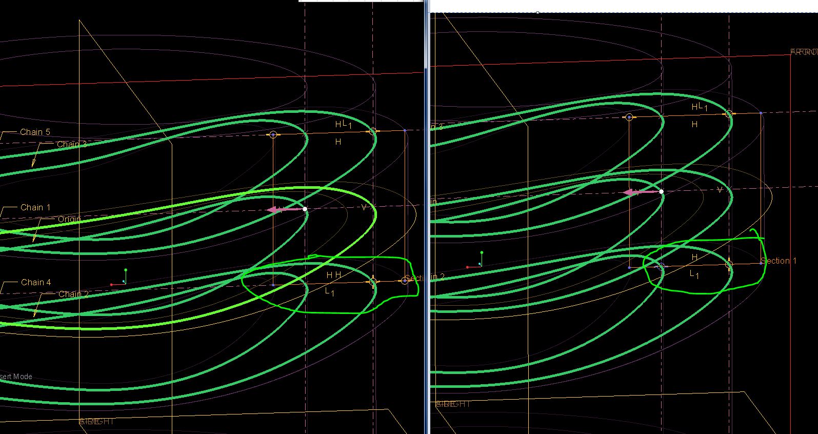
Brilliant!  Thanks Matt!  It seems so obvious when you highlight it like this

I see that I did mess up the sweep cross-section.  In the copy, the coincident constraint on the inner trajectory, whereas in the original, it is on the outer trajectory.

I suppose I still don't understand why that makes the difference for I thought these trajectory points are "horizontal" anyway...

Thank you everyone for your help.