1-Visitor
November 3, 2015
Solved

How to display reference plane or curve in mechanica analysis result?

  • November 3, 2015
  • 2 replies
  • 1266 views

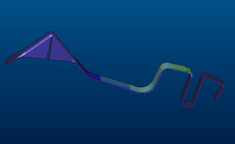
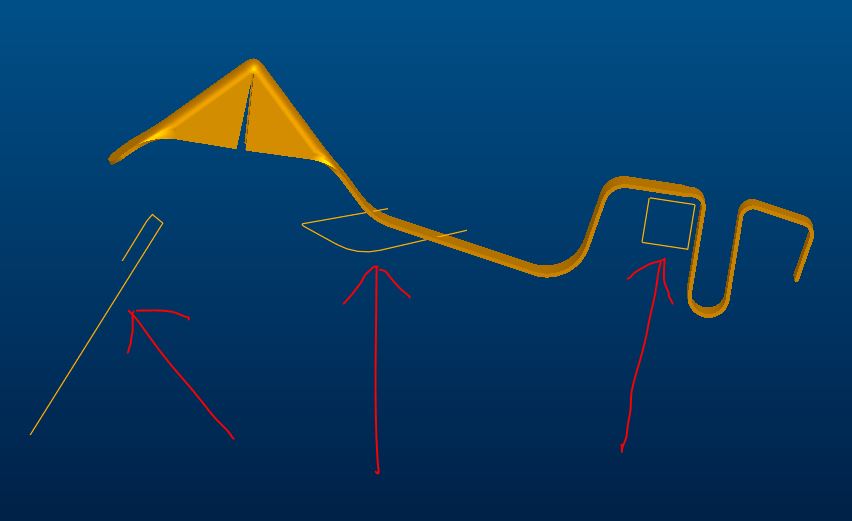
As shown in down figures.

In first figure, there are three defined curves, to act as deformation reference for the part, but in the second figure, in the mechanica analysis result, the curves will not display.

So I can not compare relative position between the part and curves after deformation.

How to make the curves displayed in the result?
1.JPG2.JPG


This thread is inactive and closed by the PTC Community Management Team. If you would like to provide a reply and re-open this thread, please notify the moderator and reference the thread. You may also use "Start a topic" button to ask a new question. Please be sure to include what version of the PTC product you are using so another community member knowledgeable about your version may be able to assist.
Best answer by mlindqvist

I would create beam elements on those curves,and make those beams rigid, either by using rigid links, or constraints. You can only view elements, not CAD geometry without elements, in results.

Another strategy is to export a VRML file of the deformed geometry and import that into the original CAD-file. 

2 replies

1-Visitor
November 3, 2015

I would create beam elements on those curves,and make those beams rigid, either by using rigid links, or constraints. You can only view elements, not CAD geometry without elements, in results.

Another strategy is to export a VRML file of the deformed geometry and import that into the original CAD-file. 

yzhu-21-VisitorAuthor
1-Visitor
November 9, 2015

Your comment seems to work, but I have not wholely been aware of your idea. I need to exercise that for times.