Section cutting plane line font is different between two like drawings but drawing configs appear to be the same.
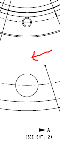
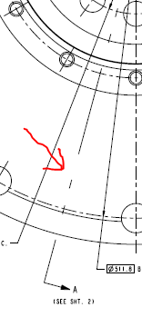
I couldn't find a better area to ask this: I have two drawings with nearly the exact same part detailed. One has a section cutting plane line font as a dense phantom line. The other has a very wide spread phantom line font that, in my opinion, does not look good on the print. I can't find any discrepancies between the two drawing configs so I'm not sure why this has changed between the two drawings. I don't think it's the size of one of the parts as the part with the preferred cutting plane line font - its casting drawing has the bad looking cutting plane line font and obviously the casting is the same size...besides stock. I don't think the PTC defaults have changed in the time it took me to finish one drawing and create the other either as, again, I don't see any differences in the drawing configs. In the Creo drawing the cutting planes look alike but as soon as I plot them on PDF or even print them directly from Creo the one changes to the spaced out phantom font. Any ideas???