

Solved
Sheet Metal Bend Centerlines shown double in drawing
The model shows a single axis for each bend line but the drawing shows two axis for each bend line. Only one of both is correct and has the bend note attached to it.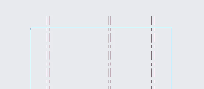
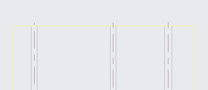

The model shows a single axis for each bend line but the drawing shows two axis for each bend line. Only one of both is correct and has the bend note attached to it.
Hi,
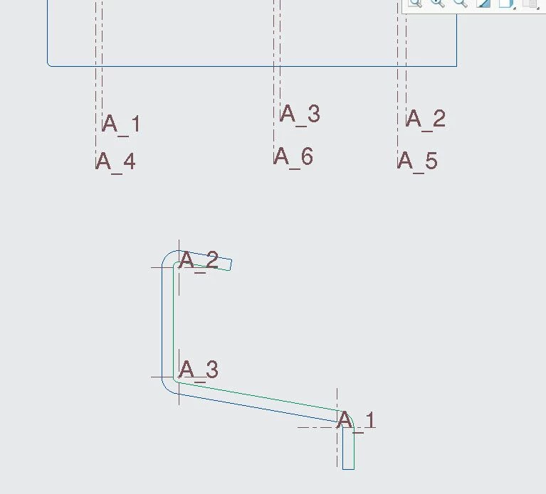
I reviewed the data and bouble bend axis display is correct and should display as per created geometry.
You created a model using extrude with rounds and three of the axis are from those rounds later part was converted to sheetmetal and a flat state was created. Hence on creating the view, three axis are for round features and rest three are bend axis. As in below image A1, A2 and A3 are round axis and A_4, A_5 and A_6 are bend axis.
No account yet? Create an account
Enter your E-mail address. We'll send you an e-mail with instructions to reset your password.