1-Visitor
January 25, 2012
Question

What's wrong with this assembly xsec?
  • January 25, 2012
  • 13 replies
  • 8545 views

01.PNG02.PNG


This thread is inactive and closed by the PTC Community Management Team. If you would like to provide a reply and re-open this thread, please notify the moderator and reference the thread. You may also use "Start a topic" button to ask a new question. Please be sure to include what version of the PTC product you are using so another community member knowledgeable about your version may be able to assist.

13 replies

1-Visitor
January 25, 2012

Hi

could you elaborate the problem you are facing with the two images

It is not quite clear to me

From the first image it seems that you are going for offset section, but you have joined first and end points(may not be required)

But actually I could not understand the exact problem you are facing

Regards

K.Mahanta

James621-VisitorAuthor
1-Visitor
January 25, 2012

Hello,

Yes, I am making an offset cross section of an assembly.

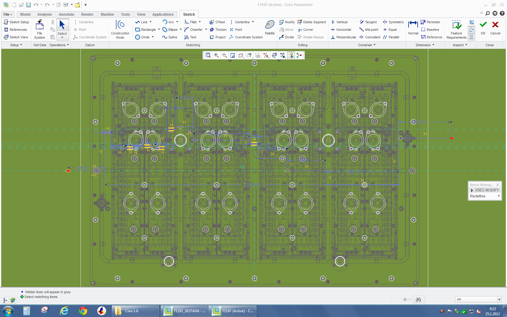
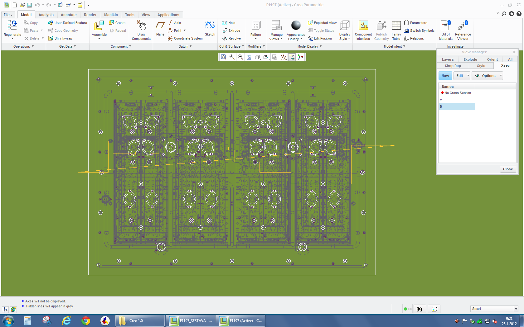
1st image shows the xsec after its completed. For some strange reason both end points of the xsec are connected with a line. This causes wrong display of xsec in assembly drawing.

2nd image shows the sketch of the xsection where everything is just how it should be as far as I know. Both ends of the line are overlaping the view and are not connected with adittional line as it is on 1st image.

In Creo 1.0 the free line points in sketches are shown in red. I am on Creo parametric 1.0 M020

Thanks.

1-Visitor
January 25, 2012

Hi

I agree with you

In Creo it shows the ends with red dots(May be a new feature)

But everything else are the same.And you should not face any problem in creating section.

In the First Picture ;you can redefine the section and remove the extra line

Are you facing any other problem in creating section?

Regards

K.Mahanta

24-Ruby III
January 27, 2012

Jakub,

just to eliminate OPENGL problem, add temporarily the following option at the end of config.pro file, restart Creo 1.0 and open your drawing.

graphics win32_gdi

Martin Hanak

James621-VisitorAuthor
1-Visitor
January 27, 2012

hi,

That additional cutting plane is still there even with graphics config changed

win32_gdi.jpg