
1-Visitor
December 17, 2020
Solved

Poor Tessallation and Broken Meshs in Creo Flow Analysis

  • December 17, 2020
  • 3 replies
  • 4325 views

Hi there,

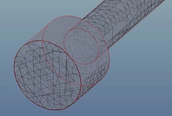
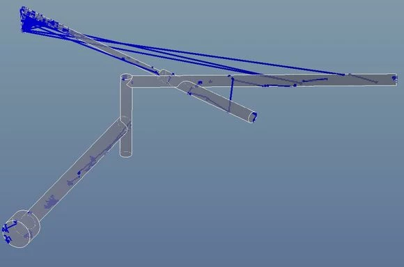
I've been trying to use the flow analysis in Creo 6 to model a relatively simple lubrication system, however my tessellation is filled with holes and producing meshes that are in a word: chaotic. I'm fairly confidant this the source of the errors in my results as having been over it several times I've been unable to find anything else that looks amiss.

Below are a couple of images to help clarify the problem.

An example of the tessellation around the input:
poor tess.jpg

An example of a mesh over the whole system:
mesh.jpg


If anyone has an advice as to how to correct this, it would be greatly appreciated.
Best answer by MartinHanak

@BenC wrote:

Hi there,

I've been trying to use the flow analysis in Creo 6 to model a relatively simple lubrication system, however my tessellation is filled with holes and producing meshes that are in a word: chaotic. I'm fairly confidant this the source of the errors in my results as having been over it several times I've been unable to find anything else that looks amiss.

Below are a couple of images to help clarify the problem.

An example of the tessellation around the input:

poor tess.jpg

An example of a mesh over the whole system:

mesh.jpg


If anyone has an advice as to how to correct this, it would be greatly appreciated.

Hi,

please ask PTC Support.

3 replies

24-Ruby III
December 20, 2020

@BenC wrote:

Hi there,

I've been trying to use the flow analysis in Creo 6 to model a relatively simple lubrication system, however my tessellation is filled with holes and producing meshes that are in a word: chaotic. I'm fairly confidant this the source of the errors in my results as having been over it several times I've been unable to find anything else that looks amiss.

Below are a couple of images to help clarify the problem.

An example of the tessellation around the input:

poor tess.jpg

An example of a mesh over the whole system:

mesh.jpg


If anyone has an advice as to how to correct this, it would be greatly appreciated.


Hi,

please ask PTC Support.

KenFarley
21-Topaz II
December 22, 2020

I've not used Creo for flow analysis, but the software I've done this with, and Creo is the same, require the user to define the geometry that encloses the fluid being analyzed. Most of my crazy results with this in the past were caused by

(1) Bad geometry that didn't really enclose the fluid volume of interest.

(2) Incorrect or incompatible boundary conditions. Bad pressures, crazy velocities, etc.

What you're showing looks to be a model of just the fluid volume? Or has the geometry been excluded from viewing?

Without knowing the model setup, it's impossible for anyone to suggest  what might be wrong and how to correct it.

BenC1-VisitorAuthor
1-Visitor
January 4, 2021

Hi Ken,

Thanks for your reply.

Creo has 2 options you can either analysis the fluid volume (what is shown) or use the existing geometry and creo will generate a fluid volume to analyse. I've attempted both methods and modelled each in multiple ways to find if it was a modelling issue. All have presented similar solutions to the pictures I've attached.


As for the boundary conditions given the simplictiy I don't think it would be this as it's a 15L/min input and all outputs are open to atm.

10-Marble
June 25, 2021

I think you need to switch to using Absolute Accuracy, with the same accuracy level in all of your Creo part and assembly files (and experiment with the accuracy tolerance set quite or very small...) and then it should create a good tessellation in the first step of the process.  You may also need to set and adjust the ENV variable called CFD_MESH_CONTROL_PERCENT, as mentioned in the following article, but annoyingly in very few CS docs.

https://community.ptc.com/t5/Analysis/Poor-meshing-results-Tesselation-in-Flow-Analysis/td-p/575064

One respondent said they will expose this variable as a parameter of tessellation in the future version, and said it will be "soon", way back in Oct 2018, but ~2.5 years later and its still not there !  What does "soon" mean ?

So maybe also take a look at :  https://www.ptc.com/en/support/article/CS335755


Only once you have a good tessellation (which you can preview...) can you possibly get a good mesh - but you will need to adjust the messing cell size values, preferably in absolute mode so you can use meaningful dimensional values, not just relative to CAD models.  Finally, you may be able to back off to reduce cell count.

13-Aquamarine
June 25, 2021

Hi 


It looks like an issue from your graphics card driver. The blue lines are not from the mesh. Please upgrade your graphics card driver and also use the latest version of creo flow analysis.