Recently active
I work in WF3.I want to move a part in an assy along a certain line which I have sketched.It is a simple sketch (straight line/tangent curve/straight line).I create a ASM-datapoint on the sketch and use "ratio" to decide the point's relative position along the sketch.The moving of the part is controlled by adjusting the ratio between 0 and 1.Now comes my problem. The datapoint will not move along the full sketch - it will only move within the segment of the sketch where I defined it. I believe I must convert the sketch to a curve which I have tried, using <insert;datum;curve;copy>. Although the resulting curve appears to follow the whole of the sketch, the result is the same. When defining the data point, it will only move within parts of the sketch.I might add that if the sketch only consists of 1 item it works as intended.How do I convert my sketch to a chain which the data point regards as one curve?Using the option "through points" will only get me an approximation.&nbs
Hello everyone We have just switched to Creo 11 from Creo 9 ( jumped 10 ) and I am finding that Creo isn't retrieving Chuck and part assemblies, and the retrieve missing component function is no longer on the right click mouse option. Does anyone have any ideas what is happening. I have checked my search.pro file and my paths are correct. I don't know if this started in Creo 10 as we jumped that release version. Thank you
This may be a silly question:- I recently started using CREO at work. I had a PC when I first got at work. They switched me out to a laptop.- I thought I remembered that CREO Versioned File Extensions (i.e. .1, .2, ... .50, .51) showed up in Windows FIle Explorer. Am I crazy?- I need to know the latest versioned file since this is how we manage rev control at our work - not Windchill here.- I remember the versioned file extensions showed up on my PC - now with my laptop I see nothing.- Is this a Window File Explorer setting - or a CREO setting?- So, when I have to upload a specific versioned file I have to use Windows sort by date to see latest.- Please help me see the actual versioned files in Windows Explorer or open/save dialog box.Thanks
I found the config option for naming a sheet metal flat pattern representation and wondering if there is one that will automatically name a flat pattern instance to some other default name. We would like the flat pattern name to be <part number>-600 like we are doing for the rep. Creo 8.0.0.0 Thanks...
I am using Creo 8, and I am having problems publishing an AR experience of one of our larger assemblies, it fails, but I do not get any helpful feedback from the status bar or the popups is there a better way to see why it is failing? I have been able to publish this assembly in the past, during a round of checks from my team we found a couple issues that were fixed on the Creo side, but when trying to publish again it is failing. I have tried to publish other smaller assemblies and they are hit or miss, I have published single part files and it is also hit or miss. I checked and it is not a firewall issue from what I can tell, but going to the https://app.ar-design.ptc.io/ site is very slow and occasionally will error out. Thanks!
I NEED HELP TO UNDERSTAND WHAT THESE CIRCLES ARE ON THE SKETCH LINES. EVERYTHING LOOKS GOOD, CLOSED LOOP AND COMPLETE CLOSED LOOP PROJECTION OF THE SKETCH LINES I AM TRYING TO PROJECT A SKETCH TO OFFSET A CURVED SURFACE, AND AN ODD SURFACE (SEE PICTURES). THESE ARE THE STEPS I'VE TAKEN:* SKETCH* PROJECT SKETCH (I ENSURED ALL PARTS OF THE PROJECTION WERE CONNECTED, AND ON ALL SURFACE(S) OF THE PROJECTION)* SKETCH-PROJECT SKETCH (SKETCH SHOWS IT IS A COMPLETE LOOP(S))* OFFSET- EXPAND (SELECTED ALL SURFACES)NOTHING, I CANNOT GET EITHER A POSITIVE OR NEGATIVE EXPANSION (OFFSET ABORTED; GEOMETRY COULD NOT BE CONSTRUCTED)I DO NOT SEE THESE CIRCLES IN THE ORIGINAL SKETCH THE GREEN OUTLINE IS ONE AREA TO PROJECT TO FOR AN OFFSET, AND THE ORANGE AREA IS ANOTHER YOUR HELP IS APPRECIATEDAIRMAN DILLARD
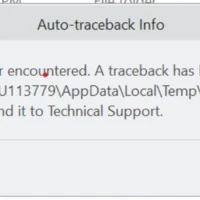
I am using Creo Parametric Release 8.0 and Datecode8.0.6.0During the rebuild of 2 separate parts I use edit references to walk through the model tree and re-define the references of each feature.For one part it works fine, but in the other part I encounter problems.Creo crashes using edit references. When using edit definition to re-define the features creo does not crash.How is this possible?What can be the root cause?Here are the errors that I facedFatal error encountered.
I have a 3D frame model and I want to add mass to a point to locate the CG of a component. The Help section says to use the Refine Model --> Mass function to do this, but I haven't been able to locate that function on the Ribbon, or in any of the Toolbars. Where is this located? https://support.ptc.com/help/creo/creo_pma/r10.0/usascii/index.html#page/simulate/simulate/add_mass_pt.html
Model and Sketch dimensions are not highlighting its only showing small square boxes
Hello, I'm using creo 9.0.8.0 and need a formula to calculate the Blank weight. Usually we write the dimensions down in a parameter like this 10x101x1. I did change it to 6 separate Parameters so that i have 3 for the number and 3 for the decimal places . I multiply the normal numbers in a relation to get the weight and merge the parameters to a single Parameter for the bom. now the problem: some of my colleges say its to complicated and time consuming to fill in those measurements and i need a simplier way of doing it. My new way to do it is by extracting the measurements from a single parameter. The Problem with this solution is that creo cant calculate it that way because it says theyre all Strings and not integers. Any ideas how to calculate it? Or make it easier? PRO_MP_MASS is showing the current weight and not the blank one. And getting the numbers from the first profile isnt an option. If you want i can provide you the current
The PRT which is the drawing based on has International System units (mm) settings. Whenever the generated DXF is opened, the Creo 9 drw convert dimensions from mm to inch and it is not intended. I'm not being able to find conversion in the drawing module. Don't know if the conversion occurs in the DXF exportation or in the drw generation from the exported DXF. Thanks
I have a fixture for nut runners where it has to be moved by robots. I have simulated the required motion in the creo mechanism. I need to know the force required for that motion. How do I find it?(view in My Videos)
I'm attempting to recreate the weldment symbol below, unfortunately I'm struggling with identifying the correct symbol. It appears to be a simple v groove weld symbol with a grind flush finish and a tail that is x4. however I can't seem to modify a simple v groove to be symmetrical and include the 3.2 identifier. Any assistance would be great. Thank you in advance.
Working in Creo 10.0 is there anyway to save the draft analysis as a .stp file with the draft analysis colors on the part? I have tried a 3D PDF but have not had any luck.
Hi,I am trying to create drawing with multiple line width and colors and printing in pdf.If i do not use pentable, everything comes in its width and colors, but model line thickness will be huge. Now if i want to use pentable, i can only print drawing with line colors as per default format setup in creo. I am successful with line widths but not colors. Please help me out if anyone knows anything about it. I have attched drw file and pentable file which i am using. I am using this configs - Use_8_plotter_pens YesPdf_use_pentable Yespen_table_file C: PTC V1_pen_table.pnt
Hello, we have been working with windchill for about a month now. I have an important question about this. Do I have the possibility to configure additional columns in the conflict window with further windchill parameters such as the name or the release status? We find it extremely annoying that only a meaningless number of the 3D model is displayed. With assemblies of 100-200 parts, of course, you don't have all the numbers in your head and have to cancel the action first and look for the numbers in the model tree so that you know which part it is and whether you can change it or whether it has already been released. I would be very grateful for any tips. Creo 7.0 + Windchill 12.0.2.13
I would like to be able to find out the reference dimension from the blue lines to my orange sketch, but the "Reference" button is greyed out. Help me please.I'm using Creo 2.0On a nearby computer, my colleague is able to add this reference measurement. I tried to import its configuration settings - it didn't help. Just in case, I will attach a file with my configuration settings.
Hi We have a crazy relation in our start part that converts the system generated PRO_MP_MASS in a Text Parameter with 3 decimal places, which can then be used to set the weight property within our PLM system, Teamcenter. Im not a fan of this relation as its about 27 lines long. I once found a new relation, shown below, on a website, but cant for the life of me remember where. Trouble is, when Ive come to try it out, its not giving the correct answer, compared to the generated mass property. Dec_P is set as a parameter to 3 RN = FLOOR((PRO_MP_MASS+(5/10^(DEC_P+1))),DEC_P)IF FLOOR(RN) == 0MASS = "0."+ITOS((RN-FLOOR(RN))*10^(DEC_P))ELSEMASS = ITOS(FLOOR(RN))+"."+ITOS((RN-FLOOR(RN))*10^(DEC_P))ENDIF
I'd like to use a custom template when creating a harness mfg drawing (as shown in the help link below, step 4), however the browse to file selection is greyed out (as shown in the attached screenshot). Does anyone know how to allow this selection? To Generate a Flattened Harness Manufacturing Drawing (ptc.com) I'm using Creo parametric 8.0.7.0. Any help is greatly appreciated!
My task: I need to model a part with multiple interfaces to an assembly. In order to do it, I created a shrinkwrap feature in my part, and brought the quilts of all solid bodies that I needed to interface with (shrinkwrap option "Autocollect all solid surfaces") . I also added more "helper" surface features to model my part. Once the geometry of my solid part is ready, I need to delete all those temporary "helper" quilts. Best solution I found:I have used the features "Thicken" and "Solidify" to create many independent solid bodies (one solid out of each quild), and eventually used feature "Remove body" to remove all solid bodies (those solids made out of quilds), only leaving one solid body which is the main geometry of the part. The question:I presume there is a better way to delete the quilds, but I couldn't find it. I also couldn't find many people asking about this problem, so I may be approaching this wrongly on the first place. Can somebody please recommend a "pro
I've loaded Creo 8.0.2.0 and CreoView Adaptors 8.0.0.0, I copied the install folder to a central location and have set my protk.dat paths to that location. I've double checked the paths in the protk.dat by using the dir command in a command window to list those files. I've done this many times before with Creo 4 and earlier, no issues. With Creo 8 I'm getting this error: Creo Toolkit registry file: C:\Users\haigh1\pro\Creo_8_Home\protk.dat: cannot spawn application `proe2pv`; read error `No such file or directory` I'm having similar errors with other toolkit applications we have. All have worked fine in Creo 4 and previously.
Hi, For some application that I am working on, I will save you the details, I would like to know what the exact mathematical motion law is behind the 'monotonic' option in mechanism. I prefer the table option in a servo motor, for creating complex movements. If so, there are three options to connect the points in the table: linear, spline and monotonic. Dynamic analysis cannot work with linear, which is quite understandable. Spline motions result to non minimum phase behavior (first move in the wrong direction before going in the right direction), so that is not usable either. Monotonic does a nice job, but I would like to compare the movement (displacement, speed and accelleration) with a physical servo motor movement (which has probably a 3-4-5 polynomen motion profile built in, but I have to check that as well). To be short: who can tell me the mathematical motion law (formula's) behind the monotonic option in mechanism. Best regards,Laurens
Hello I'm creating this post following the switch from CREO 8 to CREO 10.I make a lot of use of the offset/projection and segment uncut functions in the sketches I create, except that with the new tool this is totally broken. Here's an image to illustrate my problem : I want to remove the corner and keep the two straight lines. I was able to browse other topics where the subject of the new tool is discussed but no solution seems to have been given.Do you have any information on the subject? Would it be possible to have an option to go back to the old tool or to make it differently ? Is it possible to no longer consider the projection/offset as a loop? Thanks and have a nice day, Leo
I'm trying to create a mapkey that renames my features with an identifier from it's own dimension.For exampleRound 1, which has a radius of 5mm gets names to "R5"Hole 1 with a diameter of 10 gets renamed to "ø10"M6 hole gets renamed to "M6" Because of Creo, every featurename has to be unique even though it has a unique feature ID. So to do that I would like to add the feature ID or feature number (Any unique identifier for that specific feature) behind the name.So Round 1 with feature ID 3864 becomes "R5 (id3864)". Even better would be to make the text invisible using invisible characters but that might be too much to ask. So far I've tried everything but I can't find a way to let the mapkey copy the value of the feature or anything from the feature information window. Rounds don't even have parameters I could try to use. Things to note: We don't have OTK or Jlink and we don't use Round Sets for unrelated reasons, so the Round feature always has the same feature informat
Hi Everyone, I have a project Industrial conveyor, but i bit confused about the mechanism.... I want to create a moving object on the Belt but i am still the same issues, the moving part is not going anywhere but the belt mechanism is active. can u guys help me to solve this problem (The goal is the belt and moving object will move together). Should i use the 3D contacts and gravity?? (If yes, can u show me the tips)
Already have an account? Login
Enter your E-mail address. We'll send you an e-mail with instructions to reset your password.